Authorized Distributor
?
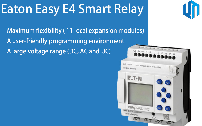
Control relays easyE4
| Product Weight | 0.25 kg |
| Product Length/Depth | 58 mm |
| Product Height | 90 mm |
| Product Width | 72 mm |
| Degree Of Protection | IP20 |
| Mounting Method | Screw fixing using fixing brackets ZB4-101-GF1 (accessories) Front build in possible Rail… |
Industrial Automation, Power Distribution, Machine Building and more.
Eaton Moeller® series EASY Control relay supplied by Eaton rated Power supply: 24 V DC (-15 %/+ 20 %) Power supply: 24 V AC (-15 %/+ 10 %) Power supply: 12 V DC (-15 %/+ 20 %) Relay outputs: max. 300 V AC/DC Inputs: shall be identical to the power supply voltage.
Key performance data includes Product type: Control relays easyE4, breaking capacity 300000 Operations at AC-15, 250 V AC, 3 A (600 Ops./h) 200000 Operations at DC-13, L/R ≦ 150 ms, 24 V DC, 1 A (500 Ops./h).
Typical applications include Industrial Automation, Power Distribution, Machine Building and more.
| General Information | |
|---|---|
| Product Name | Eaton Moeller® series EASY Control relay |
| Catalog Number | 197211 |
| EAN | 4015081939480 |
| Model Code | EASY-E4-UC-12RC1 |
| Display type | Monochrome |
| Product category | Control relays easyE4 |
| Type | easyE4 base device |
| Voltage type | AC/DC |
| Connection type | Screw terminal Ethernet: RJ45 plug, 8-pole |
| Cable type | Ethernet: CAT5 |
| Electrical Characteristics | |
|---|---|
| Duty factor | 100 % |
| Frequency counter | Cable length: ≤ 20 m (shielded) Counter frequency: ≤ 5 kHz Number: 4 (I1, I2, I3, I4) Pulse pause ratio: 1:1 Pulse shape: Square |
| Input frequency | 50/60 Hz (Digital inputs at AC) |
| Insulation resistance | According to EN IEC 61010-2-201, UL61010-2-201, CSA-C22.2 NO. 61010-2-211 |
| Lifespan, electrical | 25,000 Operations (Filament bulb load at 1000 W, 230/240 V AC) 25,000 Operations (Fluorescent lamp load 10 x 58 W at 230/240 V AC, uncompensated) 25,000 Operations (Fluorescent lamp load 10 x 58 W at 230/240 V AC, with upstream electrical device) 25,000 Operations (Filament bulb load at 500 W, 115/120 V AC) 25,000 Operations (Fluorescent lamp load 1 x 58 W at 230/240 V AC, conventional, compensated) |
| Lifespan, mechanical | 10,000,000 Operations |
| Overvoltage category | Power supply + Inputs + Extension: II Relay outputs: III |
| Rated impulse withstand voltage (Uimp) | Relay outputs: 6 kV (contact-coil) |
| Switching frequency | 10 Hz, Relay outputs 2 Hz, Resistive load/lamp load, Relay outputs 0.5 Hz, Inductive load, Relay outputs |
| Utilization category | B 300 Light Pilot Duty, UL/CSA Control Circuit Rating Codes AC R 300 Light Pilot Duty, UL/CSA Control Circuit Rating Codes DC |
| Shock resistance | 15 g, Mechanical, acc. to IEC/EN61131-2, Half-sinusoidal shock 11 ms, 18 Impacts |
| Vibration resistance | 8.4 - 150 Hz, 1 g constant acceleration 5 - 8.4 Hz, 3.5 mm constant amplitude According to IEC/EN 61131-2 |
| Burst impulse | 2 kV, I/O port 2 kV, Power supply port 1 kV, communication port According to IEC/EN 61131-2 |
| Radio interference class | Class B (EN 61000-6-3) |
| Voltage dips | 1 ms 12 V DC 10 ms at 24 V DC 20 ms at 24 V AC |
| Power consumption | 3 W |
| Power loss | 10 VA |
| Rated breaking capacity | 300000 Operations at AC-15, 250 V AC, 3 A (600 Ops./h) 200000 Operations at DC-13, L/R ≦ 150 ms, 24 V DC, 1 A (500 Ops./h) |
| Rated operational voltage | Power supply: 24 V DC (-15 %/+ 20 %) Power supply: 24 V AC (-15 %/+ 10 %) Power supply: 12 V DC (-15 %/+ 20 %) Relay outputs: max. 300 V AC/DC Inputs: shall be identical to the power supply voltage |
| Supply frequency | 50/60 Hz (± 5%) |
| Supply voltage at AC, 50 Hz - min | 20.4 VAC |
| Supply voltage at AC, 50 Hz - max | 26.4 VAC |
| Supply voltage at DC - min | 10.2 VDC |
| Supply voltage at DC - max | 28.8 VDC |
| Uninterrupted current | 1 A DC, at R 300 (UL/CSA) 8 A DC, at 24 V DC (UL/CSA) 5 A AC, max. thermal continuous current cos ϕ = 1 at B 300 (UL/CSA) 10 A AC, at 240 V AC (UL/CSA) |
| Short-circuit protection | ≥ 1A (T), Fuse, Power supply |
| Input current | 1.8 mA (I5 - I8, at 24 V DC,at signal 1) 3.3 mA (I1 - I4, at 24 V DC,at signal 1) 3.5 mA (I1 - I4, at 24 V AC,at signal 1) 1.8 mA (I5 - I8, at 24 V AC,at signal 1) 0.9 mA (I5 - I8, at 12 V DC,at signal 1) 1.75 mA (I1 - I4, at 12 V DC,at signal 1) < 1 mA (Analog inputs) |
| Input voltage | Condition 0: ≤ 5 V DC (Digital inputs, 12 V DC) Condition 0: ≤ 5 V DC (Digital inputs, 24 V DC) Condition 1: ≥ 15 V DC (Digital inputs, 24 V DC) Condition 1: ≥ 8 V DC (Digital inputs, 12 V DC) Condition 0: ≤ 5 V AC (Digital inputs, 24 V AC) Condition 1: ≥ 15 V AC (Digital inputs, 24 V AC) |
| Making/breaking capacity | 28/28 VA (DC, at R 300) 3600/360 VA (AC, at B 300) |
| Safe isolation | Relay outputs: 300 V AC, Between two contacts Relay outputs: 300 V AC, Between coil and contact |
| Equipment heat dissipation, current-dependent Pvid | 1 W |
| Heat dissipation capacity Pdiss | 0 W |
| Heat dissipation per pole, current-dependent Pvid | 0 W |
| Static heat dissipation, non-current-dependent Pvs | 3 W |
| 10.2.2 Corrosion resistance | Meets the product standard's requirements. |
| 10.2.3.2 Verification of resistance of insulating materials to normal heat | Meets the product standard's requirements. |
| 10.2.4 Resistance to ultra-violet (UV) radiation | Meets the product standard's requirements. |
| 10.9.2 Power-frequency electric strength | Is the panel builder's responsibility. |
| 10.9.3 Impulse withstand voltage | Is the panel builder's responsibility. |
| 10.11 Short-circuit rating | Is the panel builder's responsibility. |
| Mechanical & Physical | |
|---|---|
| Product Length/Depth | 58 mm |
| Product Height | 90 mm |
| Product Width | 72 mm |
| Product Weight | 0.25 kg |
| Fitted with: | Display Real time clock Relay output Keypad Timer |
| Degree of protection | IP20 |
| Mounting method | Screw fixing using fixing brackets ZB4-101-GF1 (accessories) Front build in possible Rail mounting possible Top-hat rail fixing (according to IEC/EN 60715, 35 mm) Wall mounting/direct mounting |
| Protection | B16 circuit breaker or 8 A (T) fuse, Protection of an Output relay |
| Height of fall (IEC/EN 60068-2-32) - max | 0.3 m |
| Mounting position | Vertical Horizontal |
| Terminal capacity | 0.2 - 4 mm² (AWG 22 - 12), solid 0.2 - 2.5 mm², flexible with ferrule 0.2 - 2.5 mm², flexible without ferrule |
| Screwdriver size | 3.5 x 0.6 mm, Terminal screw |
| Tightening torque | 0.6 Nm, Screw terminals |
| Cable length | Digital inputs (DC): ≤ 100 m (unshielded) Digital inputs (AC): ≤ 40 m (unshielded) Analog inputs: ≤ 30 m (shielded) |
| Protection against polarity reversal | Yes |
| 10.3 Degree of protection of assemblies | Meets the product standard's requirements. |
| 10.5 Protection against electric shock | Does not apply, since the entire switchgear needs to be evaluated. |
| 10.7 Internal electrical circuits and connections | Is the panel builder's responsibility. |
| 10.8 Connections for external conductors | Is the panel builder's responsibility. |
| 10.9.4 Testing of enclosures made of insulating material | Is the panel builder's responsibility. |
| Environmental & Compliance | |
|---|---|
| Compliances | Eaton supports the product until its end of life |
| Certifications | UL File No.: E205091 CE UL hazardous location group B (hydrogen) UL hazardous location group C (ethylene) UL hazardous location division 2 UL hazardous location group A (acetylene) UL hazardous location class I UL hazardous location group D (propane) cULus Ordinary Location DNV TAA00002HT cULus Hazard Location UL File No.: E523283 EN 61131-2 IEC 61131-2 EN IEC 61000-6-3 IEC 61000-6-3 EN IEC 61010-2-201 IEC 61010-2-201 UL 61010-1 UL 61010-2-201 CSA C22.2 No. 61010-1 CSA C22.2 No. 61010-2-201 UL 121201 CSA C22.2 No. 213 |
| Display temperature - min | 0 °C |
| Display temperature - max | 55 °C |
| Pollution degree | 2 |
| Ambient operating temperature - min | -25 °C |
| Ambient operating temperature - max | 55 °C |
| Ambient storage temperature - min | -40 °C |
| Ambient storage temperature - max | 70 °C |
| Relative humidity | 5 - 95 % (IEC 60068-2-30, IEC 60068-2-78) |
| 10.10 Temperature rise | The panel builder is responsible for the temperature rise calculation. Eaton will provide heat dissipation data for the devices. |
| Additional Specifications | |
|---|---|
| Catalog Notes | Accuracy of the real-time clock depending on ambient air temperature - fluctuations of up to ± 5 s/day (± 0.5 h⁄year) are possible |
| Features | Expandable Display indication of 6 lines x 16 characters Networkable (Ethernet) |
| Indication | LCD-display used as status indication of digital I/Os |
| Protocol | Modbus TCP |
| Residual ripple | Power supply: ≤ 5 % |
| Resolution | 12 Bit (value 0 - 4095, Analog inputs) |
| Software | EASYSOFT-SWLIC/easySoft |
| Used with | easyE4 |
| Drop and topple | 50 mm Drop height, Drop to IEC/EN 60068-2-31 |
| Air pressure | 795 - 1080 hPa (operation) |
| Environmental conditions | Clearance in air and creepage distances according to EN 50178, EN 61010-2-201, UL61010-2-201, CSA-C22.2 NO. 61010-2-201 Condensation: prevent with appropriate measures |
| Air discharge | 8 kV |
| Contact discharge | 6 kV |
| Electromagnetic fields | 10 V/m at 0.08 - 1.0 GHz (according to IEC/EN 61131-2) 3 V/m at 1.0 - 6 GHz (according to IEC/EN 61131-2) |
| Immunity to line-conducted interference | 10 V (according to IEC/EN 61131-2) |
| Surge rating | 1 kV, Line-to-Line, Power supply port 2 kV, Line-to-Earth, Power supply port 1 kV, Line-to-Line, Input port 2 kV, Line-to-Earth, Input port 1 kV, Line-to-Earth, communication port According to IEC/EN 61131-2 |
| Data transfer rate | 10/100 MBit/s |
| Accuracy | ± 2 s/day, Real-time clock to inputs (± 0.2 h⁄Year) ± 2 %, (I5, I6, I7, I8) ± 0.12 V, of actual value, within a single device (Analog Inputs) ± 1 %, Repetition accuracy of timing relays (of values) ± 3 %, of actual value, two easy devices (Analog Inputs) |
| Conversions | Each CPU cycle for Analog inputs |
| Delay time | 0.015 ms typ., Digital inputs 12 V DC (I1 - I8), Delay time from 1 to 0, Debounce OFF 0.015 ms typ., Digital inputs 24 V DC (I1 - I8), Delay time from 1 to 0, Debounce OFF 0.015 ms typ., Digital inputs 24 V DC (I1 - I8), Delay time from 0 to 1, Debounce OFF 20 ms typ., Digital inputs 12 V DC (I1 - I8), Delay time from 1 to 0, Debounce ON 20 ms typ., Digital inputs 12 V DC (I1 - I8), Delay time from 0 to 1, Debounce ON 20 ms typ., Digital inputs 24 V DC (I1 - I8), Delay time from 0 to 1, Debounce ON 20 ms typ., Digital inputs 24 V DC (I1 - I8), Delay time from 1 to 0, Debounce ON 0.015 ms typ., Digital inputs 12 V DC (I1 - I8), Delay time from 0 to 1, Debounce OFF |
| Incremental counter | Number of counter inputs: 2 (I1 + I2, I3 + I4) Value range: -2147483648 to +2147483647 Pulse shape: Square Pulse pause ratio: 1:1 Signal offset: 90° Counter frequency: ≤ 5 kHz Cable length: ≤ 20 m (shielded) |
| Input | Voltage (DC) |
| Input impedance | Analog: 13.3 kΩ |
| Number of inputs (analog) | 0 4 |
| Number of inputs (digital) | 4 8 |
| Number of outputs (analog) | 0 |
| Number of outputs (digital) | 4 |
| Output | 4 Relay Outputs min. recommended load: 12 V AC/DC > 500 mA |
| Parallel switching | Not permitted |
| Rapid counter inputs | Counter frequency: ≤ 10 kHz Value range: -2147483648 to +2147483647 Cable length: ≤ 20 m (shielded) Pulse pause ratio: 1:1 Pulse shape: Square Number of rapid counter inputs: 4 (I1, I2, I3, I4) |
| Signal range | 0 - 10 V DC, Analog inputs |
| Potential isolation | Power supply + Inputs + Extension interface against Outputs: yes POW+Inputs+Extension interface vs. Ethernet+Functional Earth: yes Outputs against Ethernet + Functional Earth: yes Outputs against each other: yes |
| 10.2.3.1 Verification of thermal stability of enclosures | Meets the product standard's requirements. |
| 10.2.3.3 Resist. of insul. mat. to abnormal heat/fire by internal elect. effects | Meets the product standard's requirements. |
| 10.2.5 Lifting | Does not apply, since the entire switchgear needs to be evaluated. |
| 10.2.6 Mechanical impact | Does not apply, since the entire switchgear needs to be evaluated. |
| 10.2.7 Inscriptions | Meets the product standard's requirements. |
| 10.4 Clearances and creepage distances | Meets the product standard's requirements. |
| 10.6 Incorporation of switching devices and components | Does not apply, since the entire switchgear needs to be evaluated. |
| 10.12 Electromagnetic compatibility | Is the panel builder's responsibility. |
| 10.13 Mechanical function | The device meets the requirements, provided the information in the instruction leaflet (IL) is observed. |
Note: Specifications are taken from the official Eaton EASY-E4-UC-12RC1 datasheet.
Official technical documentation for the EASY-E4-UC-12RC1.
Typical applications of the EASY-E4-UC-12RC1.
Other models in the Eaton All Eaton Products product series.