Authorized Distributor
?
Residual current circuit breaker
| Product Weight | 0.22 kg |
| Product Length/Depth | 76 mm |
| Product Height | 80 mm |
| Product Width | 35 mm |
Switchgear for export to North America (UL-listed)
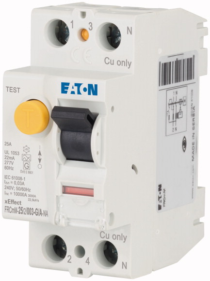
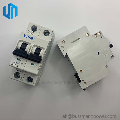
Eaton Moeller series xEffect - FRCmM-NA RCCB. Residual current circuit breaker (RCCB), 25A, 2p, 30mA, type G/A, UL
Key technical data includes Features: Additional equipment possible; Residual current circuit breaker; Fitted with:: Interlocking device; Functions: Short-time delayed tripping.
| General Information | |
|---|---|
| Product Name | Eaton Moeller series xEffect - FRCmM-NA RCCB |
| Catalog Number | 167119 |
| Model Code | FRCMM-25/2/003-G/A-NA |
| EAN | 4015081636211 |
| Product Length/Depth | 76 mm |
| Product Height | 80 mm |
| Product Width | 35 mm |
| Product Weight | 0.22 kg |
| Compliances | RoHS conform |
| Certifications | UL 1053; EN 61008; IEC 61008; ÖVE E 8601; EN45545-2; IEC 61373 |
| Catalog Notes | Additionally protects against special forms of residual pulsating DC which have not been smoothed. |
| Amperage Rating | 25 A |
| Application | Switchgear for export to North America (UL-listed) |
| Fault current rating | 30 mA |
| Impulse withstand current | 3 kA (8/20 μs) surge-proof |
| Number of poles | Two-pole |
| Rated short-circuit strength | 5 kA (UL, as per CSA); 10 kA with back-up fuse |
| Sensitivity type | Pulse-current sensitive |
| Tripping time | Short time-delayed; 10 ms delay at 50 Hz; 8 ms delay at 60 Hz |
| Type | Current test marks as per inscription; Maximum operating temperature is 55 °C: Starting at 40 °C, the max. permissible continuous current decreases by 3% for every 1 °C; The maximum operating current of back-up fuse must not exceed the residual current circuit breaker's rated operational current |
| Additional information | |
|---|---|
| Features | Additional equipment possible; Residual current circuit breaker |
| Fitted with: | Interlocking device |
| Functions | Short-time delayed tripping |
| Special features | FRCmM-NA; Residual current circuit breakers; Type G/A (ÖVE E 8601) |
| Used with | Type G/A (ÖVE E 8601); FRCmM-NA; Residual current circuit breakers |
| Standards & Design Verification | |
|---|---|
| 10.10 Temperature rise | The panel builder is responsible for the temperature rise calculation. Eaton will provide heat dissipation data for the devices. |
| 10.11 Short-circuit rating | Is the panel builder's responsibility. The specifications for the switchgear must be observed. |
| 10.12 Electromagnetic compatibility | Is the panel builder's responsibility. The specifications for the switchgear must be observed. |
| 10.13 Mechanical function | The device meets the requirements, provided the information in the instruction leaflet (IL) is observed. |
| 10.2.2 Corrosion resistance | Meets the product standard's requirements. |
| 10.2.3.1 Verification of thermal stability of enclosures | Meets the product standard's requirements. |
| 10.2.3.2 Verification of resistance of insulating materials to normal heat | Meets the product standard's requirements. |
| 10.2.3.3 Resist. of insul. mat. to abnormal heat/fire by internal elect. effects | Meets the product standard's requirements. |
| 10.2.4 Resistance to ultra-violet (UV) radiation | Meets the product standard's requirements. |
| 10.2.5 Lifting | Does not apply, since the entire switchgear needs to be evaluated. |
| 10.2.6 Mechanical impact | Does not apply, since the entire switchgear needs to be evaluated. |
| 10.2.7 Inscriptions | Meets the product standard's requirements. |
| 10.3 Degree of protection of assemblies | Does not apply, since the entire switchgear needs to be evaluated. |
| 10.4 Clearances and creepage distances | Meets the product standard's requirements. |
| 10.5 Protection against electric shock | Does not apply, since the entire switchgear needs to be evaluated. |
| 10.6 Incorporation of switching devices and components | Does not apply, since the entire switchgear needs to be evaluated. |
| 10.7 Internal electrical circuits and connections | Is the panel builder's responsibility. |
| 10.8 Connections for external conductors | Is the panel builder's responsibility. |
| 10.9.2 Power-frequency electric strength | Is the panel builder's responsibility. |
| 10.9.3 Impulse withstand voltage | Is the panel builder's responsibility. |
| 10.9.4 Testing of enclosures made of insulating material | Is the panel builder's responsibility. |
| Ambient operating temperature - max | 40 °C |
| Ambient operating temperature - min | -25 °C |
| Equipment heat dissipation, current-dependent | 2 W |
| Heat dissipation capacity | 0 W |
| Heat dissipation per pole, current-dependent | 1 W |
| Rated operational current for specified heat dissipation (In) | 25 A |
| Static heat dissipation, non-current-dependent | 0 W |
| Electrical Characteristics | |
|---|---|
| Admissible back-up fuse overload - max | 25 A gG/gL |
| Frequency rating | 50 Hz / 60 Hz |
| Leakage current type | A |
| Lifespan, electrical | 4000 operations |
| Overvoltage tested - max | 530 V |
| Pick-up current | 22 mA |
| Pollution degree | 2 |
| Rated fault current - max | 0.03 A |
| Rated fault current - min | 0.03 A |
| Rated impulse withstand voltage (Uimp) | 4 kV |
| Rated insulation voltage (Ui) | 440 V |
| Rated operational voltage (Ue) - max | 277 V |
| Rated residual making and breaking capacity | 500 A |
| Rated short-time withstand current (Icw) | 10 kA |
| Short-circuit rating | Max. admissible back-up fuse: 63 A gG/gL, 70 A class J fuse (UL) |
| Surge current capacity | 3 kA |
| Test circuit range | 184 V AC - 250 V AC, 196 V AC - 305 V AC (UL) |
| Voltage rating (IEC/EN 60947-2) | 240 V AC / 415 V AC |
| Voltage rating (UL) | 480Y/277 V, 60 Hz |
| Mechanical & Physical | |
|---|---|
| Ambient humdity range | 5 - 95 % |
| Built-in depth | 70.5 mm |
| Built-in width (number of units) | 35 mm (2 SU) |
| Climatic proofing | 25-55 °C / 90-95% relative humidity according to IEC 60068-2 |
| Connectable conductor cross section (multi-wired) - max | 16 mm² |
| Connectable conductor cross section (multi-wired) - min | 1.5 mm² |
| Connectable conductor cross section (solid-core) - max | 35 mm² |
| Connectable conductor cross section (solid-core) - min | 1.5 mm² |
| Contact position indicator color | Red / green |
| Degree of protection | IP20, IP40 with suitable enclosure; IP20 |
| Frame | 45 mm |
| Lifespan, mechanical | 10000 operations |
| Mounting Method | Quick attachment with 2 latch positions for DIN-rail IEC/EN 60715; DIN rail |
| Mounting position | As required |
| Permitted storage and transport temperature - max | 60 °C |
| Permitted storage and transport temperature - min | -35 °C |
| Status indication | White / blue |
| Terminal capacity (cable) | M5 (with cross-recessed screw as defined in EN ISO 4757-Z2, PZ2) |
| Terminal capacity (solid wire) | 1.5 mm² - 35 mm² |
| Terminal capacity (stranded cable) | 16 mm² (2x) |
| Terminal protection | Finger and hand touch safe, DGUV VS3, EN 50274 |
| Terminals (top and bottom) | Lift terminals |
| Width in number of modular spacings | 2 |
Note: Specifications are taken from the official Eaton FRCMM-25/2/003-G/A-NA product data sheet.
Official technical documentation for the FRCMM-25/2/003-G/A-NA.
Typical applications of the FRCMM-25/2/003-G/A-NA.
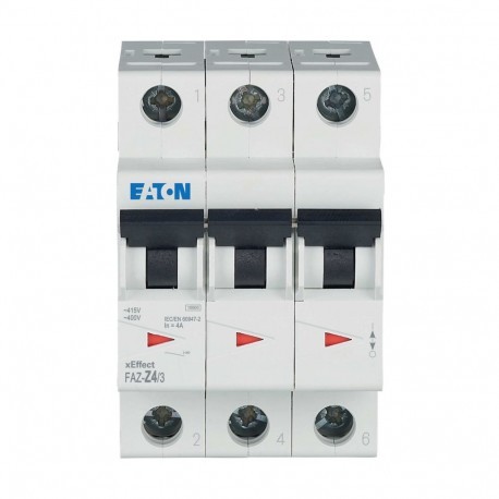
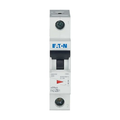
Other models in the Eaton Miniature Circuit Breakers product series.