Authorized Distributor
?
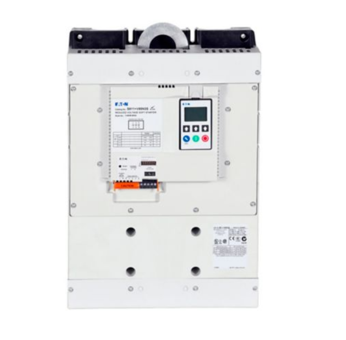
S811 Soft starter
| Product Weight | 41.4 kg |
| Product Length/Depth | 187.8 mm |
| Product Height | 420.8 mm |
| Product Width | 280.6 mm |
3-phase motors: Yes Soft starting of three-phase asynchronous motors
Eaton S811 Soft starter, 650 A, 200 - 600 V AC, Us= 24 V DC, with control unit, Frame size V
Key technical data includes Altitude: Above 2000 m with 0.5 % derating per 100 m Max. 2000 m; Ambient operating temperature - max: 50 °C; Ambient storage temperature - max: 70 °C.
| General Information | |
|---|---|
| Product Name | Eaton S811 Soft starter |
| Catalog Number | 169002 |
| Model Code | S811+V65N3S |
| EAN | 4015081654963 |
| Product Length/Depth | 187.8 mm |
| Product Height | 420.8 mm |
| Product Width | 280.6 mm |
| Product Weight | 41.4 kg |
| Compliances | CE Marked |
| Certifications | IEC 60947-4-2 UL Listed EN 60947-4-2 UL Recognized CSA file No. 3211-06 CSA Certified for Elevator Duty IEC/EN 60947-4-2 CSA File No.: LR 353 UL File No.: E202571 UL CSA Class No.: 3211-06 CCC CSA22.2-14-1995 GB14048 UL 508 UL Category Control No.: NMFT CE CSA-C22.2 No. 14 C-Tick CSA |
| Class | Adjustable |
| Connection to SmartWire-DT | No |
| Degree of protection | IP00 NEMA Other |
| Frame size | V |
| Mains voltage - max | 600 V |
| Mains voltage - min | 200 V |
| Mounting position | As required |
| Overvoltage category | II |
| Pollution degree | 3 |
| Radio interference class | Class A (EN 55011) |
| Rated impulse withstand voltage (Uimp) | 4000 V |
| Rated insulation voltage (Ui) | 660 V |
| Shock resistance | 15 g, Mechanical |
| Startup class | CLASS 10 (star-delta replacement) CLASS 30 (6 x Iₑ for 30 s) CLASS 20 (heavy starting duty 3 x Iₑ for 45 s) |
| Suitable for | Branch circuits, not as BCPD, (UL/CSA) |
| Type | Soft starter for three-phase loads, with control unit |
| Used with | Three-phase motors |
| Voltage type | DC |
| Control circuit | |
|---|---|
| Current consumption | 1400 mA, Control circuit, Regulator supply 10 A/150 ms, Control circuit, Regulator supply at peak performance (close bypass) at 24 V DC 100 mA, Control circuit, Digital inputs, External 24 V (no-load) 150 mA, Control circuit, Digital inputs, External 24 V |
| Drop-out time | 100 ms, DC operated |
| Drop-out voltage | 0 - 3 V, DC operated |
| Pick-up time | 100 ms at DC |
| Pick-up voltage | 21.6 - 26.4 V DC |
| Rated control supply voltage (Us) at AC, 50 Hz - max | 0 V |
| Rated control supply voltage (Us) at AC, 50 Hz - min | 0 V |
| Rated control supply voltage (Us) at AC, 60 Hz - max | 0 V |
| Rated control supply voltage (Us) at AC, 60 Hz - min | 0 V |
| Rated control supply voltage (Us) at DC - max | 24 V |
| Rated control supply voltage (Us) at DC - min | 24 V |
| Standards & Design Verification | |
|---|---|
| 10.10 Temperature rise | The panel builder is responsible for the temperature rise calculation. Eaton will provide heat dissipation data for the devices. |
| 10.11 Short-circuit rating | Is the panel builder's responsibility. The specifications for the switchgear must be observed. |
| 10.12 Electromagnetic compatibility | Is the panel builder's responsibility. The specifications for the switchgear must be observed. |
| 10.13 Mechanical function | The device meets the requirements, provided the information in the instruction leaflet (IL) is observed. |
| 10.2.2 Corrosion resistance | Meets the product standard's requirements. |
| 10.2.3.1 Verification of thermal stability of enclosures | Meets the product standard's requirements. |
| 10.2.3.2 Verification of resistance of insulating materials to normal heat | Meets the product standard's requirements. |
| 10.2.3.3 Resist. of insul. mat. to abnormal heat/fire by internal elect. effects | Meets the product standard's requirements. |
| 10.2.4 Resistance to ultra-violet (UV) radiation | Meets the product standard's requirements. |
| 10.2.5 Lifting | Does not apply, since the entire switchgear needs to be evaluated. |
| 10.2.6 Mechanical impact | Does not apply, since the entire switchgear needs to be evaluated. |
| 10.2.7 Inscriptions | Meets the product standard's requirements. |
| 10.3 Degree of protection of assemblies | Does not apply, since the entire switchgear needs to be evaluated. |
| 10.4 Clearances and creepage distances | Meets the product standard's requirements. |
| 10.5 Protection against electric shock | Does not apply, since the entire switchgear needs to be evaluated. |
| 10.6 Incorporation of switching devices and components | Does not apply, since the entire switchgear needs to be evaluated. |
| 10.7 Internal electrical circuits and connections | Is the panel builder's responsibility. |
| 10.8 Connections for external conductors | Is the panel builder's responsibility. |
| 10.9.2 Power-frequency electric strength | Is the panel builder's responsibility. |
| 10.9.3 Impulse withstand voltage | Is the panel builder's responsibility. |
| 10.9.4 Testing of enclosures made of insulating material | Is the panel builder's responsibility. |
| Equipment heat dissipation, current-dependent Pvid | 25 W |
| Heat dissipation capacity Pdiss | 0 W |
| Heat dissipation per pole, current-dependent Pvid | 0 W |
| Rated operational current for specified heat dissipation (In) | 650 A |
| Static heat dissipation, non-current-dependent Pvs | 25 W |
| Main conducting paths | |
|---|---|
| Overload cycle | AC-53a: 4.0 - 32: 99 - 3 |
| Rated operational current (Ie) at AC-53 | 650 A |
| Rated operational current (Ie) at AC-53, in-delta | 1125 A |
| Rated operational voltage (Ue) - max | 600 V |
| Rated operational voltage (Ue) - min | 200 V |
| Short-circuit protection rating | NZMN4-ME875, Type “1” coordination, Main conducting paths |
| Supply frequency | 50/60 Hz, fLN, Main circuit |
| Voltage rating - max | 600 V |
| Motor Rating & Protection | |
|---|---|
| Assigned motor power at 200/208 V, 60 Hz, 3-phase | 200 HP |
| Assigned motor power at 220/230 V, 60 Hz, 3-phase | 250 HP |
| Assigned motor power at 460/480 V, 60 Hz, 3-phase | 500 HP |
| Assigned motor power at 600 V, 60 Hz, 3-phase | 600 HP |
| Assigned motor power in-delta at 220/230 V, 60 Hz | 450 HP |
| Assigned motor power in-delta at 460/480 V, 60 Hz | 850 HP |
| Assigned motor power in-delta at 575/600 V, 60 Hz | 1100 HP |
| Rated operational power at 220/230 V, 50 Hz | 200 kW |
| Rated operational power at 400 V, 50 Hz | 315 kW |
| Rated operational power at 500 V, 50 Hz | 450 kW |
| Rated operational power in-delta at 220/230 V, 50 Hz | 200 kW |
| Rated operational power in-delta at 400 V, 50 Hz | 630 kW |
| Rated operational power in-delta at 500 V, 50 Hz | 450 kW |
| Additional Specifications | |
|---|---|
| Fault memory | 10 Faults |
| Fitted with: | Display Internal bypass contacts Motor overload protection Internal bypass |
| Functions | Potential isolation between power and control sections Soft start function Suppression of closing transients Suppression of DC components for motors Overload monitoring Min. ramp time 1 s - fast switching (semiconductor contactor) Current limitation Underload monitoring Single direction |
| Interfaces | Modbus RTU (built-in) |
| Application | 3-phase motors: Yes Soft starting of three-phase asynchronous motors |
| Delay time | 0 - 60 s, Soft start function, Ramp times |
| Kickstart | Max. 2000 ms (Kickstart Duration) 100% (Kickstart voltage) |
| Ramp/run-up time | 180 s |
| Start voltage | Max. 85 %, Soft start function, Start voltage = turn-off voltage |
| Altitude | Above 2000 m with 0.5 % derating per 100 m Max. 2000 m |
| Ambient operating temperature - max | 50 °C |
| Ambient storage temperature - max | 70 °C |
| Ambient operating temperature - min | -30 °C |
| Ambient storage temperature - min | -50 °C |
| Climatic proofing | Damp heat, cyclic, to IEC 60068-2-30 Damp heat, constant, to IEC 60068-2-3 |
| Screwdriver size | 0.6 x 3.5 mm, Terminal screws, Control circuit cables |
| Terminal capacity (flexible with ferrule) | 4 x (70 - 240) mm², Main cables 1 x (2.5 - 4) mm², Control circuit cables 2 x (1 - 2.5) mm², Control circuit cables 6 x (120 - 240) mm², Main cables 2 x (120 - 240) mm², Main cables |
| Terminal capacity (solid) | 1 x (2.5 - 4) mm², Control circuit cables 4 x (70 - 240) mm², Main cables 2 x (1 - 2.5) mm², Control circuit cables 2 x (120 - 240) mm², Main cables 6 x (120 - 240) mm², Main cables |
| Terminal capacity (solid/stranded AWG) | 2 x (14 - 12), Control circuit cables 6 x (4 - 500 kcmil), Main cables 1 x (14 - 12), Control circuit cables 4 x (4 - 500 kcmil), Main cables 2 x (4 - 500 kcmil), Main cables |
| Terminal capacity (stranded) | 1 x (2.5 - 4) mm², Control circuit cables 2 x (1 - 2.5) mm², Control circuit cables 2 x (120 - 240) mm², Main cables 4 x (70 - 240) mm², Main cables 6 x (120 - 240) mm², Main cables |
| Tightening torque | 0.4 Nm, Screw terminals, Control circuit cables |
| Input current | 4 - 20 mA (Analog inputs) |
| Number of inputs | 1 (current input) |
| Number of outputs | 2 Relay Outputs (programmable) |
| Output voltage | 120 V AC/DC (relay outputs) |
| Protection | Finger and back-of-hand proof, Protection against direct contact |
| Rated control voltage (Uc) | 24 V DC (-10 %/+10 %) 24 V DC |
| Rated operational current (Ie) at AC-11 | 3 A |
Note: Specifications are taken from the official Eaton S811+V65N3S product data sheet.
Official technical documentation for the S811+V65N3S.
Typical applications of the S811+V65N3S.
Other models in the Eaton All Eaton Products product series.