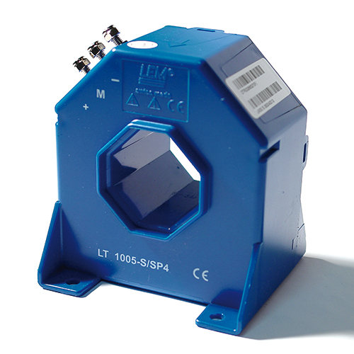
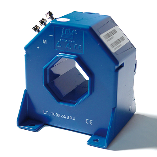
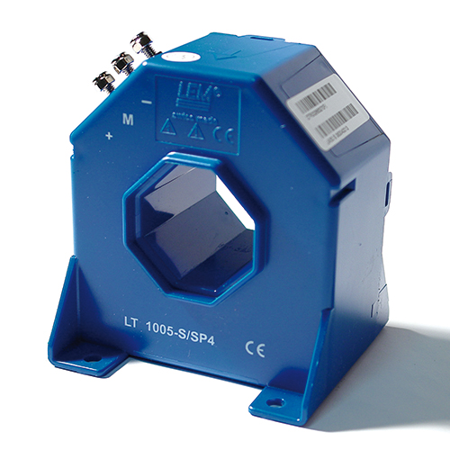
 Authorized Distributor
?
Closed loop (compensated)
| Primary Current, Measuring Range | −6000 ... 6000 A |
| Secondary Nominal RMS Current | −800 ... 800 mA |
| Electrical Offset Current | ±0.8 mA @ 25 °C |
| Isolation Test Voltage (pri-sec) | 12 kV (pri-sec) |
| Creepage Distance | 68 mm |
| Operating Temperature Range | −40 ... 70 °C |
Single or three phase inverters, Propulsion and braking choppers, Propulsion converters, Auxiliary converters, High power drives, Substations. Standard, EN 50155: 2021. Application Domain, Railway (fixed installations and onboard).
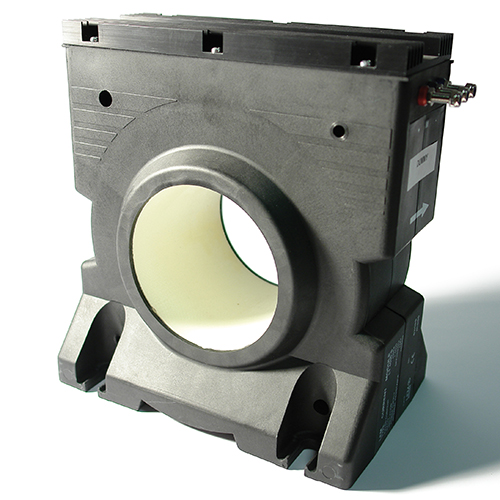
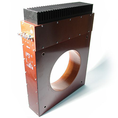
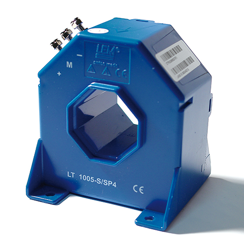
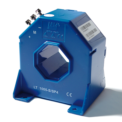
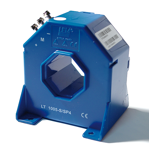
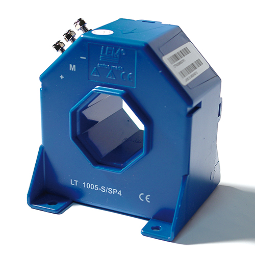
The LT 4000-S/SP35 is a closed loop (compensated) current transducer from LEM for the electronic measurement of current: DC, AC, pulsed..., with galvanic isolation.
It offers excellent accuracy, very good linearity, low temperature drift and wide frequency bandwidth. Typical applications include Single or three phase inverters, Propulsion and braking choppers, Propulsion converters and Auxiliary converters.
Key characteristics from the official datasheet: linearity error 0.2 % of IPN; operating temperature −40 ... 70 °C.
| General Information | |
|---|---|
| Manufacturer | LEM |
| Product Series | LT |
| Product Reference | LT 4000-S/SP35 |
| Primary Nominal Current | −4000 ... 4000 A |
| Supply Voltage | ±21 ... ±26.4 V |
| Measurement | current: DC, AC, pulsed... |
| Mounting | Panel Mount |
| Application Domain | Railway (fixed installations and onboard) |
| Electrical Data — LT 4000-S/SP35 | |
|---|---|
| Primary Nominal AC RMS Current (IPN) | −4000 ... 4000 A (f ≤ 100 Hz) |
| Primary Current, Measuring Range (IPM) | −6000 ... 6000 A |
| Measuring Resistance (RM) | 0 Ω (see figure 1) |
| Secondary Nominal RMS Current (ISN) | −800 ... 800 mA |
| Resistance of Secondary Winding (RS) | 12.5 ... 13 Ω @ 25 °C |
| Number of Secondary Turns (NS) | 5000 |
| Number of Turns, Test Winding (NT) | 1000 |
| Maximum Test Current (IT max) | 1 A |
| DC Supply Voltage (±UC) | ±21 ... ±26.4 V |
| DC Current Consumption (IC) | 25 ... 29 mA + IS × NP/NS |
| Accuracy & Dynamic Performance | |
|---|---|
| Total Error (εtot) @ 25 °C | ±0.5 % @ IPN (25 °C) |
| Total Error (εtot) @ −40 ... 70 °C | ±0.8 % @ IPN (−40 ... 70 °C) |
| Electrical Offset Current (IO E) | ±0.8 mA @ 25 °C |
| Temperature Variation of IO E (IO T) | ±0.4 ... ±0.8 mA (referred to 25 °C) |
| Magnetic Offset Current (IO M) | 0.2 mA (after 3 × IPN) |
| Linearity Error (εL) @ 25 °C | < 0.1 % @ 25 °C |
| Linearity Error (εL) @ −40 ... 70 °C | < 0.2 % @ −40 ... 70 °C |
| RMS Noise referred to primary (Ino) | 90 ppm of IPN (1 Hz ... 10 MHz) |
| Delay Time to 10 % of Final Output (tD 10) | < 1 µs |
| Delay Time to 90 % of Final Output (tD 90) | < 1 µs |
| Frequency Bandwidth (−1 dB) | 10 kHz (−1 dB) |
| Frequency Bandwidth (−3 dB) | 130 kHz (−3 dB) |
| Insulation Coordination | |
|---|---|
| RMS Voltage for AC Insulation Test (50 Hz, 1 min) Ud (pri-sec) | 12 kV (pri-sec) |
| RMS Voltage for AC Insulation Test (50 Hz, 1 min) Ud (sec-test) | 1 kV (sec-test) |
| Impulse Withstand Voltage (1.2/50 µs) UNi | 17.7 kV |
| Partial Discharge Test Voltage (q < 10 pC) Um t | 5760 V |
| Clearance (dCI) | 68 mm |
| Creepage Distance (dCp) | 68 mm |
| Case Material | V0 according to UL 94 |
| Comparative Tracking Index (CTI) | 600 |
| Rated Insulation RMS Voltage (UNm) | 4800 V (IEC 62497-1) |
| Environmental & Mechanical Characteristics | |
|---|---|
| Ambient Operating Temperature (TA) | −40 ... 70 °C |
| Ambient Storage Temperature (TA st) | −50 ... 85 °C |
| Equipment Operating Temperature Class (EN 50155) | OT4 |
| Switch-on Extended Operating Temperature Class (EN 50155) | ST0 |
| Rapid Temperature Variation Class (EN 50155) | H1 |
| Conformal Coating Type (EN 50155) | PC2 |
| Relative Humidity (RH) | 20 ... 80 % (non-condensing) |
| Shock & Vibration (EN 61373) | 1B |
| Mass (m) | 6000 g |
| Ingress Protection Rating | IP40 |
| Altitude | 2000 m |
| Standards & Certifications | |
|---|---|
| EN 50155 | 2021. |
Note: Specifications are taken from the official LT 4000-S/SP35 datasheet. Parameters that could not be confirmed from the datasheet are marked UNVERIFIED.
Official technical documentation for the LT 4000-S/SP35.
Outline dimensions, pin layout and connection diagrams of the LT 4000-S/SP35 are shown below.
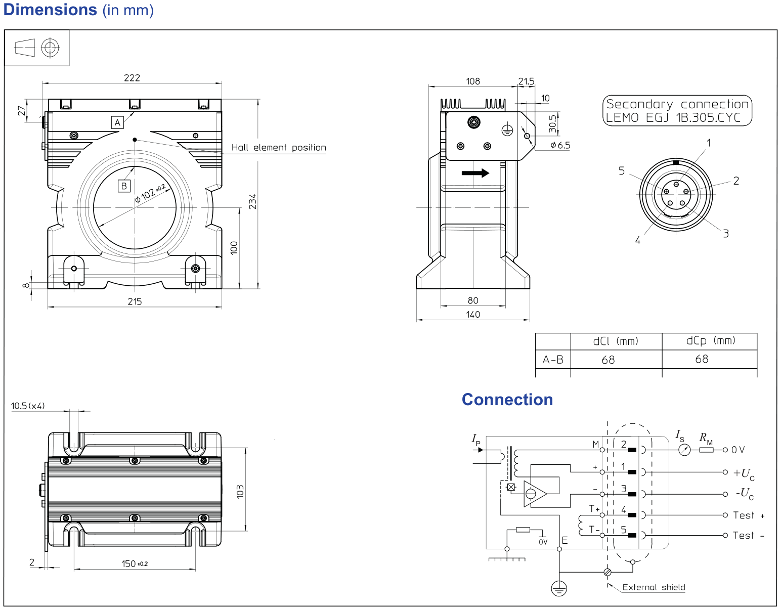
| Outline Dimensions & Mechanical Data | |
|---|---|
| Mass | 6000 g |
| Resistance of Secondary Winding (RS) | 12.5 ... 13 Ω @ 25 °C |
| Number of Turns, Test Winding (NT) | 1000 |
| Case Material | V0 according to UL 94 |
| Ingress Protection Rating | IP40 |
Note: All dimensions are in millimetres. Refer to the official datasheet for the complete dimension drawing.
Typical applications of the LT 4000-S/SP35.
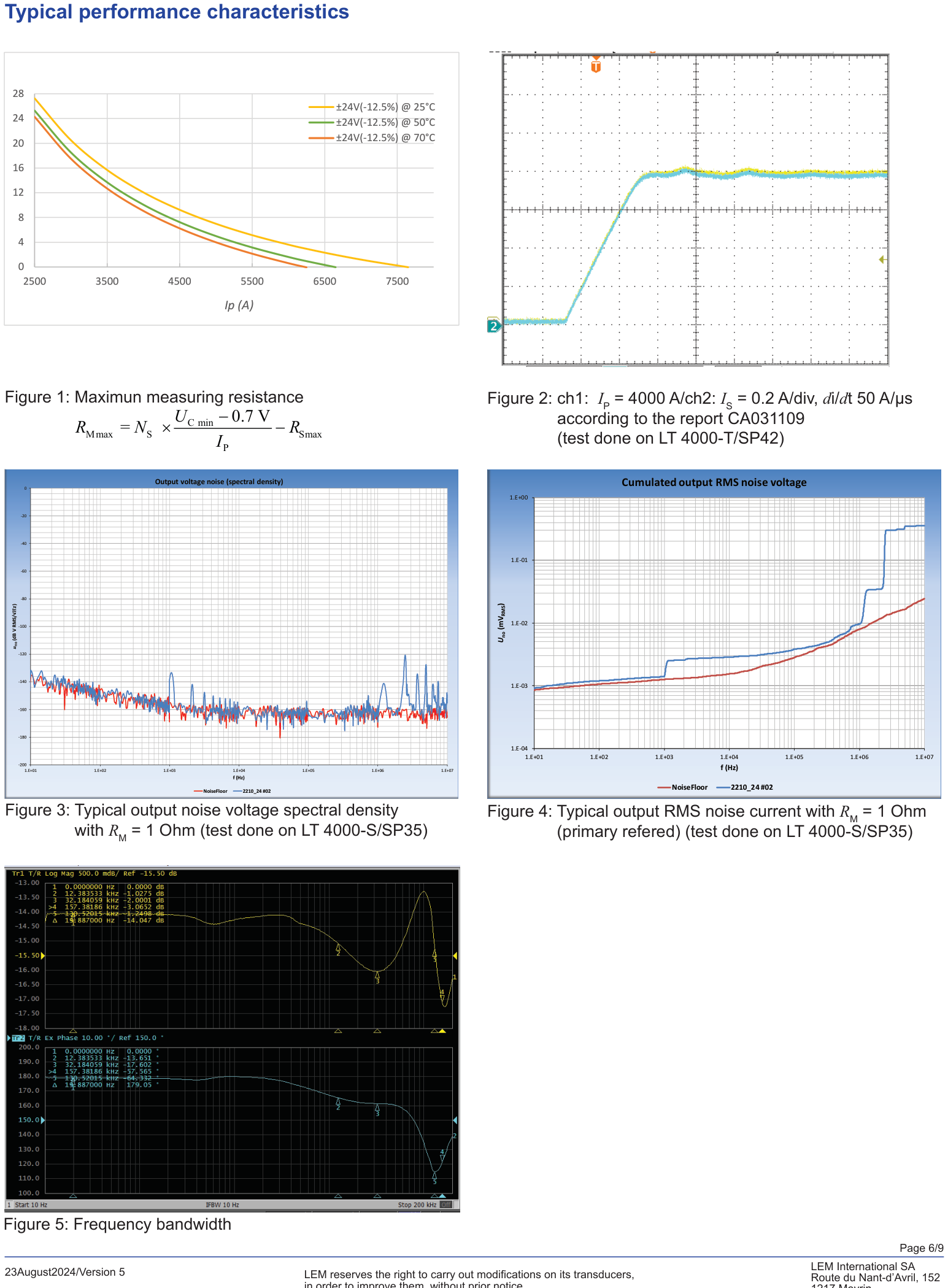
The characteristic curves of the LT 4000-S/SP35 from the official datasheet are shown below.
| Accuracy & Dynamic Characteristics | |
|---|---|
| Total Error (εtot) @ 25 °C | ±0.5 % @ IPN (25 °C) |
| Total Error (εtot) @ −40 ... 70 °C | ±0.8 % @ IPN (−40 ... 70 °C) |
| Linearity Error (εL) @ 25 °C | < 0.1 % @ 25 °C |
| Linearity Error (εL) @ −40 ... 70 °C | < 0.2 % @ −40 ... 70 °C |
| Frequency Bandwidth (−1 dB) | 10 kHz (−1 dB) |
| Frequency Bandwidth (−3 dB) | 130 kHz (−3 dB) |
Note: Refer to the datasheet for the complete set of characteristic curves.
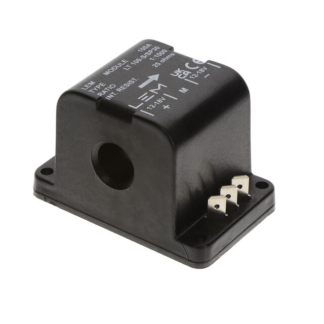
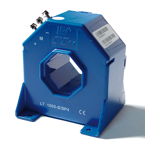
Other models of the LT Series share the same measurement principle, mounting concept and output interface family.