Authorized Distributor
?
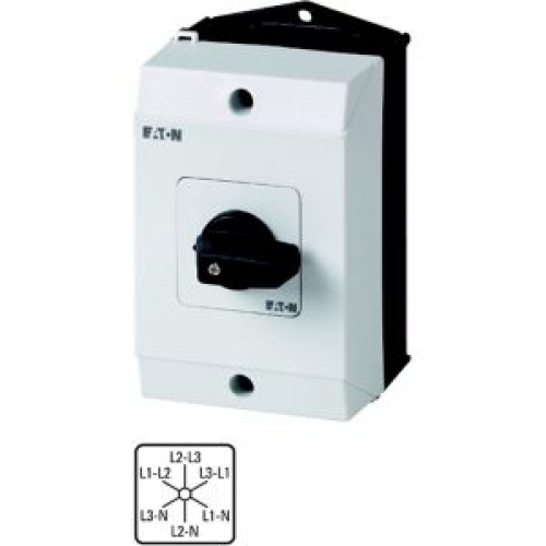
Voltmeter selector switch
| Product Weight | 0.288 kg |
| Product Length/Depth | 137 mm |
| Product Height | 122 mm |
| Product Width | 80 mm |
| Degree Of Protection | IP65 NEMA 2 |
| Number Of Poles | 3 |
Machine Control, Panel Isolation, Position Sensing and more.
Eaton Moeller® series T0 Voltmeter selector switch supplied by Eaton rated 11.5 A at 690 V.
Key performance data includes Product type: Voltmeter selector switch, breaking capacity 100 A.
Typical applications include Machine Control, Panel Isolation, Position Sensing and more.
| General Information | |
|---|---|
| Product Name | Eaton Moeller® series T0 Voltmeter selector switch |
| Catalog Number | 207119 |
| Model Code | T0-3-15924/I1 |
| EAN | 4015082071196 |
| Global Catalog | 207119 |
| Product Type | Voltmeter selector switch |
| Type | Voltmeter selector switch |
| Product Category | Control switches |
| Switch function type | 3 x phase-N, 3 x phase-phase |
| Electrical Characteristics | |
|---|---|
| 10.11 Short-circuit rating | Is the panel builder's responsibility. The specifications for the switchgear must be observed. |
| 10.2.2 Corrosion resistance | Meets the product standard's requirements. |
| 10.2.3.2 Verification of resistance of insulating materials to normal heat | Meets the product standard's requirements. |
| 10.2.4 Resistance to ultra-violet (UV) radiation | UV resistance only in connection with protective shield. |
| 10.9.2 Power-frequency electric strength | Is the panel builder's responsibility. |
| 10.9.3 Impulse withstand voltage | Is the panel builder's responsibility. |
| Operating frequency | 1200 Operations/h |
| Rated impulse withstand voltage (Uimp) | 6000 V AC |
| Equipment heat dissipation, current-dependent Pvid | 0 W |
| Heat dissipation capacity Pdiss | 0 W |
| Heat dissipation per pole, current-dependent Pvid | 0.6 W |
| Rated short-time withstand current (Icw) | 320 A, Contacts, 1 second |
| Rated conditional short-circuit current (Iq) | 6 kA |
| Overvoltage category | III |
| Lifespan, mechanical | 400,000 Operations |
| Safe isolation | 440 V AC, Between the contacts, According to EN 61140 |
| Rated operational current (Ie) | 20 A at AC-3, 400 V star-delta 15.6 A at AC-3, 500 V star-delta 20 A at AC-3, 230 V star-delta 8.5 A at AC-3, 690 V star-delta |
| Shock resistance | 15 g, Mechanical, According to IEC/EN 60068-2-27, Half-sinusoidal shock 20 ms |
| Rated breaking capacity at 220/230 V (cos phi to IEC 60947-3) | 100 A |
| Rated breaking capacity at 400/415 V (cos phi to IEC 60947-3) | 110 A |
| Rated breaking capacity at 500 V (cos phi to IEC 60947-3) | 80 A |
| Rated breaking capacity at 660/690 V (cos phi to IEC 60947-3) | 60 A |
| Rated making capacity up to 690 V (cos phi to IEC/EN 60947-3) | 130 A |
| Rated operational current (Ie) at AC-21, 440 V | 20 A |
| Rated operational current (Ie) at AC-23A, 230 V | 13.3 A |
| Rated operational current (Ie) at AC-23A, 400 V, 415 V | 13.3 A |
| Rated operational current (Ie) at AC-23A, 500 V | 13.3 A |
| Rated operational current (Ie) at AC-23A, 690 V | 7.6 A |
| Rated operational current (Ie) at AC-3, 220 V, 230 V, 240 V | 11.5 A |
| Rated operational current (Ie) at AC-3, 380 V, 400 V, 415 V | 11.5 A |
| Rated operational current (Ie) at AC-3, 500 V | 9 A |
| Rated operational current (Ie) at AC-3, 660 V, 690 V | 4.9 A |
| Short-circuit protection rating | 20 A gG/gL, Fuse, Contacts |
| Rated operational current (Ie) at DC-1, load-break switches l/r = 1 ms | 10 A |
| Rated operational current (Ie) at DC-13, control switches L/R = 50 ms | 10 A |
| Rated operational current (Ie) at DC-21, 240 V | 1 A |
| Rated operational current (Ie) at DC-23A, 120 V | 5 A |
| Rated operational current (Ie) at DC-23A, 24 V | 10 A |
| Rated operational current (Ie) at DC-23A, 240 V | 5 A |
| Rated operational current (Ie) at DC-23A, 48 V | 10 A |
| Rated operational current (Ie) at DC-23A, 60 V | 10 A |
| Rated operational current for specified heat dissipation (In) | 20 A |
| Rated operational power at AC-23A, 220/230 V, 50 Hz | 3 kW |
| Rated operational power at AC-23A, 400 V, 50 Hz | 5.5 kW |
| Rated operational power at AC-23A, 500 V, 50 Hz | 7.5 kW |
| Rated operational power at AC-23A, 690 V, 50 Hz | 5.5 kW |
| Rated operational power at AC-3, 415 V, 50 Hz | 5.5 kW |
| Rated operational power at AC-3, 690 V, 50 Hz | 4 kW |
| Rated operational power star-delta at 220/230 V, 50 Hz | 5.5 kW |
| Rated operational power star-delta at 380/400 V, 50 Hz | 7.5 kW |
| Rated operational power star-delta at 500 V, 50 Hz | 7.5 kW |
| Rated operational power star-delta at 690 V, 50 Hz | 5.5 kW |
| Rated operational voltage (Ue) at AC - max | 690 V |
| Rated uninterrupted current (Iu) | 20 A |
| Static heat dissipation, non-current-dependent Pvs | 0 W |
| Voltage per contact pair in series | 60 V |
| Uninterrupted current | Rated uninterrupted current Iu is specified for max. cross-section. |
| Mechanical & Physical | |
|---|---|
| Product Length/Depth | 137 mm |
| Product Height | 122 mm |
| Product Width | 80 mm |
| Product Weight | 0.288 kg |
| 10.3 Degree of protection of assemblies | Does not apply, since the entire switchgear needs to be evaluated. |
| 10.5 Protection against electric shock | Does not apply, since the entire switchgear needs to be evaluated. |
| 10.7 Internal electrical circuits and connections | Is the panel builder's responsibility. |
| 10.8 Connections for external conductors | Is the panel builder's responsibility. |
| 10.9.4 Testing of enclosures made of insulating material | Is the panel builder's responsibility. |
| Fitted with: | Control unit Black thumb grip and front plate |
| Enclosure material | Plastic |
| Mounting position | As required |
| Mounting method | Surface mounting |
| Number of poles | 3 |
| Degree of protection | IP65 NEMA 2 |
| Number of contacts | 6 |
| Screw size | M3.5, Terminal screw |
| Tightening torque | 8.8 lb-in, Screw terminals 1 Nm, Screw terminals |
| Number of contacts in series at DC-21A, 240 V | 1 |
| Number of contacts in series at DC-23A, 120 V | 3 |
| Number of contacts in series at DC-23A, 24 V | 1 |
| Number of contacts in series at DC-23A, 240 V | 5 |
| Number of contacts in series at DC-23A, 48 V | 2 |
| Number of contacts in series at DC-23A, 60 V | 3 |
| Terminal capacity (flexible with ferrule) | 1 x (0.75 - 2.5) mm², ferrules to DIN 46228 2 x (0.75 - 2.5) mm², ferrules to DIN 46228 |
| Terminal capacity (solid/stranded) | 2 x (1 - 2.5) mm² 1 x (1 - 2.5) mm² |
| Environmental & Compliance | |
|---|---|
| Certifications | IEC/EN 60204 IEC/EN 60947 VDE 0660 IEC/EN 60947-3 |
| 10.10 Temperature rise | The panel builder is responsible for the temperature rise calculation. Eaton will provide heat dissipation data for the devices. |
| Pollution degree | 3 |
| Climatic proofing | Damp heat, constant, to IEC 60068-2-78 Damp heat, cyclic, to IEC 60068-2-30 |
| Ambient operating temperature - max | 40 °C |
| Ambient operating temperature - min | -25 °C |
| Ambient operating temperature (enclosed) - max | 40 °C |
| Ambient operating temperature (enclosed) - min | -25 °C |
| Additional Specifications | |
|---|---|
| Catalog Notes | Rated Short-time Withstand Current (Icw) for a time of 1 second |
| Actuator function | Without 0 (Off) position Maintained |
| 10.12 Electromagnetic compatibility | Is the panel builder's responsibility. The specifications for the switchgear must be observed. |
| 10.13 Mechanical function | The device meets the requirements, provided the information in the instruction leaflet (IL) is observed. |
| 10.2.3.1 Verification of thermal stability of enclosures | Meets the product standard's requirements. |
| 10.2.3.3 Resist. of insul. mat. to abnormal heat/fire by internal elect. effects | Meets the product standard's requirements. |
| 10.2.5 Lifting | Does not apply, since the entire switchgear needs to be evaluated. |
| 10.2.6 Mechanical impact | Does not apply, since the entire switchgear needs to be evaluated. |
| 10.2.7 Inscriptions | Meets the product standard's requirements. |
| 10.4 Clearances and creepage distances | Meets the product standard's requirements. |
| 10.6 Incorporation of switching devices and components | Does not apply, since the entire switchgear needs to be evaluated. |
| Number of contact units | 3 |
| Device construction | Surface mounting |
| Control circuit reliability | 1 failure per 100,000 switching operations statistically determined, at 24 V DC, 10 mA) |
| Inscription | " Phase/Phase-Phase/N " |
| Functions | Measurement between phases possible Measuring between phase and N-neutral possible |
| Load rating | 2 x Iₑ (with intermittent operation class 12, 25 % duty factor) 1.3 x Iₑ (with intermittent operation class 12, 60 % duty factor) 1.6 x Iₑ (with intermittent operation class 12, 40 % duty factor) |
| Safety parameter (EN ISO 13849-1) | B10d values as per EN ISO 13849-1, table C.1 |
| Switching angle | 60 ° |
| Design | 15924 |
Note: Specifications are taken from the official Eaton T0-3-15924/I1 datasheet.
Official technical documentation for the T0-3-15924/I1.
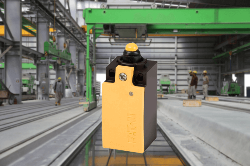
Typical applications of the T0-3-15924/I1.
Other models in the Eaton Switches & Cam Switches product series.