 Authorized Distributor
?
Voltage Transducer DVC 1000-B U = 1000 V
| Supply Voltage | ±15 ... ±24 V |
| Operating Temperature Range | −40 ... 85 °C |
| Isolation Test Voltage | 4.26 kV |
| Primary Nominal RMS Current (IPN) | 1000 V |
| Current Consumption (IC) | 12 ... ±15 mA |
| Resistance of Primary Winding (RP) | 12.6 MΩ |
EN 50155: 2021, EN 50121-3-2: 2016, IEC 62497-1: 2010, IEC 61000-6-2: 2016, IEC 61000-6-4: 2016, IEC 61800-3: 2005, IEC 61010-1: 2010, IEC 61800-5-1: 2007, IEC 62109-1: 2010, UL 508: 2018. Application Domain, Industrial or Railway (fixed installations and onboard). page 1/13 out modifications on its transducers, LEM International SA Route du Nant-d’Avril, 152 www.lem.com
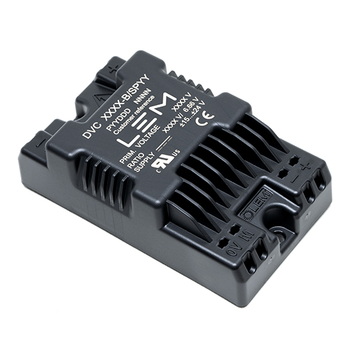
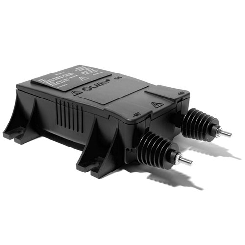
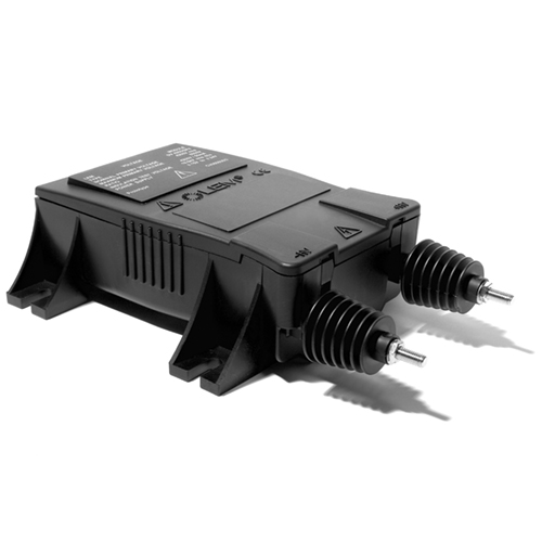
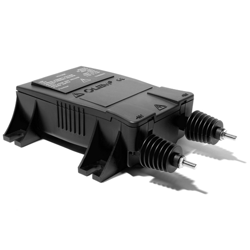
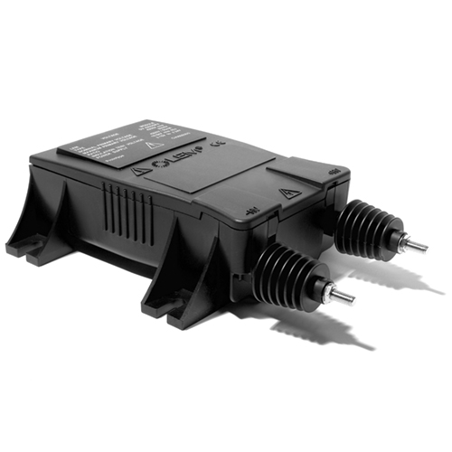
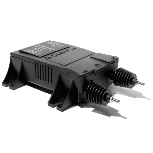
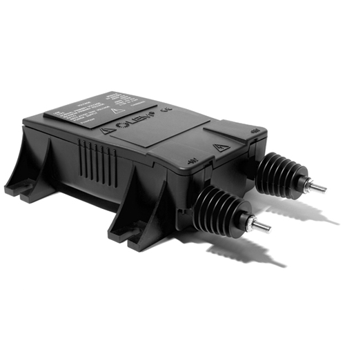
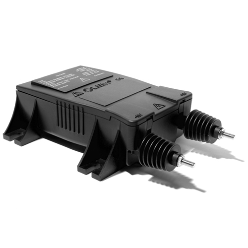
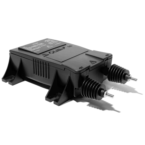
The DVC 1000-B is a None current transducer from LEM for the electronic measurement of voltage: DC, AC, pulsed..., with galvanic isolation, delivering an instantaneous output voltage of Min -10 / Max 10 V.
It offers excellent accuracy and low temperature drift. Typical applications include EN 50155: 2021, EN 50121-3-2: 2016, IEC 62497-1: 2010 and IEC 61000-6-2: 2016.
Key characteristics from the official datasheet: linearity error -0.2 ... 0.2 % of IPN; operating temperature −40 ... 85 °C.
| General Information | |
|---|---|
| Manufacturer | LEM |
| Product Series | DVC |
| Product Reference | DVC 1000-B |
| Nominal Primary Voltage | 1000 V |
| Primary Nominal Current | 1000 V |
| Supply Voltage | ±15 ... ±24 V |
| Measurement | voltage: DC, AC, pulsed... |
| Mounting | — |
| Application Domain | Industrial or Railway (fixed installations and onboard) |
| Electrical Data — DVC 1000-B | |
|---|---|
| Primary Nominal RMS Current (IPN) | 1000 V |
| Supply Voltage (UC) | ±15 ... ±24 V |
| Current Consumption (IC) | 12 ... ±15 mA |
| Resistance of Primary Winding (RP) | 12.6 MΩ |
| Primary nominal DC voltage (continuous) (UPNDC) | Typ 1000 V |
| Primary nominal AC RMS voltage (continuous) (UPNAC) | Typ 1000 V |
| Primary voltage, measuring range (UPM) | Min -1500 / Max 1500 V |
| Load resistance (RL) | Min 2000 Ω |
| Secondary nominal RMS voltage (USN) | Typ 6.66 V |
| Secondary voltage (US) | Min -10 / Max 10 V |
| DC supply voltage (UC) | Min ±15 / Typ ±20 / Max ±24 V |
| U Rise time of (10 % ... 90 %) C (trise) | Max 100 ms |
| Total error (εtot) | Min -1.7 / Max 1.7 % |
| U Temperature variation of referred to primary O (UOET) | Min -3.00 / Max 3.00 V |
| Electrical offset voltage referred to primary (UOE) | Min -6.00 / Max 6.00 V |
| Sensitivity (S) | Typ 6.6 mV/V |
| Sensitivity error (εS) | Min -1 / Max 1 % |
| Temperature variation of sensitivity error (εST) | Min -0.4 / Max 0.4 % |
| Linearity error (εL) | Min -0.2 / Max 0.2 U % of P M |
| RMS noise voltage 100 Hz … 100 kHz referred to primary (Uno) | Typ 300 mV |
| Start-up time (tstart) | Typ 40 ms |
| Resistance of primary circuit (RP) | Typ 12.6 MΩ |
| Absolute Maximum Ratings | |
|---|---|
| (U Maximum DC supply voltage = 0 V, 0.1 s) P (±ÛCmax) | ±28 V |
| Absolute Maximum Ratings | |
|---|---|
| ⎓ Maximum DC supply voltage (working) (− 40 … + 85 °C) (±UCmax) | ±25.2 V |
| Absolute Maximum Ratings | |
|---|---|
| voltag⎓e Electrostatic discharge (HBM - Human Body Model) (UESDHBM) | 4 kV |
| Absolute Maximum Ratings | |
|---|---|
| Maximum DC common mode voltage (UU+HV+HV−|UUand−|HV+HV−) | ≤ 1.5 kV |
| Accuracy & Dynamic Performance | |
|---|---|
| Linearity Error (εL) | -0.2 ... 0.2 % of IPN |
| Electrical Offset Voltage (VO E) @ IP = 0 | -6.00 ... 6.00 V |
| Response Time to 90 % of IPN Step | 12 µs |
| Insulation Coordination | |
|---|---|
| RMS Voltage for AC Insulation Test (50 Hz, 1 min) Ud | 4.26 kV |
| Impulse Withstand Voltage (1.2/50 µs) UNi | 7.84 kV |
| Creepage Distance (dCp) | 9.0 mm |
| Clearance (dCI) | 9.0 mm |
| Comparative Tracking Index (CTI) | 600 |
| Mean failure rate (λ) | Typ 1/1029866 h-1 |
| RMS voltage for AC insulation test at 50 Hz (Ud) | 4.26 kV |
| Impulse withstand voltage 1.2/50 μs (UNi) | 7.84 kV |
| (q Partial discharge RMS test voltage < 10 pC) m (Ut) | 1650 V |
| Case material | V0 |
| Application example RMS voltage line-to-neutral | 600 V |
| Application example System voltage RMS | 600 V |
| Application example Rated insulation RMS voltage | 600 V |
| Application example Rated insulation RMS voltage (UNm) | 500 V |
| Operating voltage | 1000 V |
| Environmental & Mechanical Characteristics | |
|---|---|
| Ambient Operating Temperature (TA) | −40 ... 85 °C |
| Ambient Storage Temperature (TA st) | −50 ... 90 °C |
| Mass (m) | 57 g |
| Relative humidity (RH) | Max 95 % |
| Ingress protection rating | Typ IP20 |
| Altitude | Max 1) 2000 m |
| Pollution degree | Max 2) PD3 |
| Standards & Certifications | |
|---|---|
| EN 50155 | Compliance |
| EN 50121-3-2 | Compliance |
| IEC 62497-1 | Compliance |
| IEC 61000-6-2 | Compliance |
| IEC 61000-6-4 | Compliance |
| IEC 61800-3 | Compliance |
| IEC 61010-1 | Compliance |
| IEC 61800-5-1 | Compliance |
| IEC 62109-1 | Compliance |
| UL 508 | 2018. |
Note: Specifications are taken from the official DVC 1000-B datasheet. Parameters that could not be confirmed from the datasheet are marked UNVERIFIED.
Official technical documentation for the DVC 1000-B.
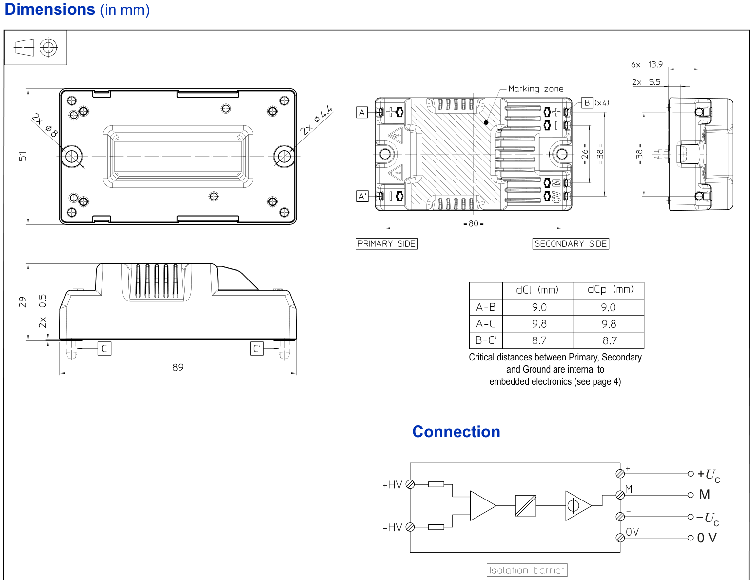
Outline dimensions, pin layout and connection diagrams of the DVC 1000-B are shown below.
| Outline Dimensions & Mechanical Data | |
|---|---|
| Mass | 57 g |
| Resistance of Primary Winding (RP) | 12.6 MΩ |
| Case material | V0 |
| Ingress protection rating | Typ IP20 |
Note: All dimensions are in millimetres. Refer to the official datasheet for the complete dimension drawing.
Typical applications of the DVC 1000-B.
The characteristic curves of the DVC 1000-B from the official datasheet are shown below.
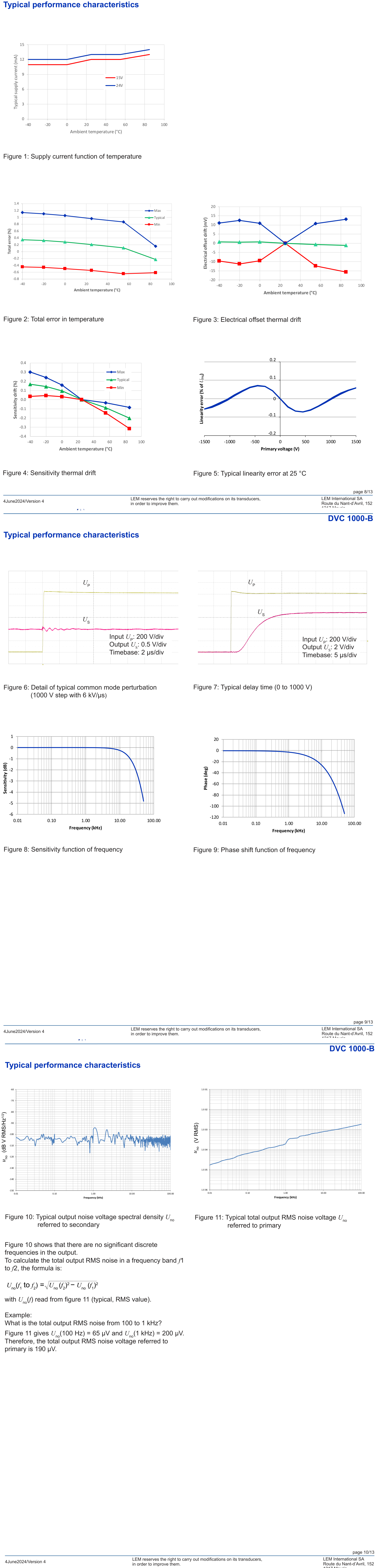
| Accuracy & Dynamic Characteristics | |
|---|---|
| Secondary voltage (US) | Min -10 / Max 10 V |
| U Rise time of (10 % ... 90 %) C (trise) | Max 100 ms |
| Total error (εtot) | Min -1.7 / Max 1.7 % |
| Sensitivity (S) | Typ 6.6 mV/V |
| Sensitivity error (εS) | Min -1 / Max 1 % |
| Temperature variation of sensitivity error (εST) | Min -0.4 / Max 0.4 % |
| Linearity error (εL) | Min -0.2 / Max 0.2 U % of P M |
| Response Time to 90 % of IPN Step | 12 µs |
| Reference Conditions | |
|---|---|
| Ambient Temperature (TA) | 25 °C, unless otherwise noted |
| Output Load Resistance (RL) | Min 2000 Ω |
Note: Refer to the datasheet for the complete set of characteristic curves.
Other models of the DV Series share the same measurement principle, mounting concept and output interface family.