Authorized Distributor
?
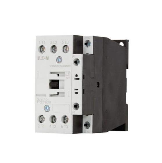
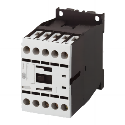
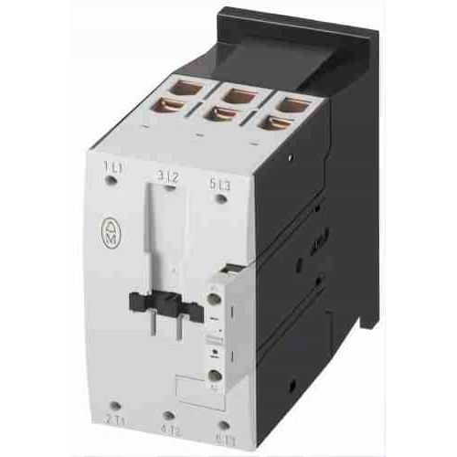
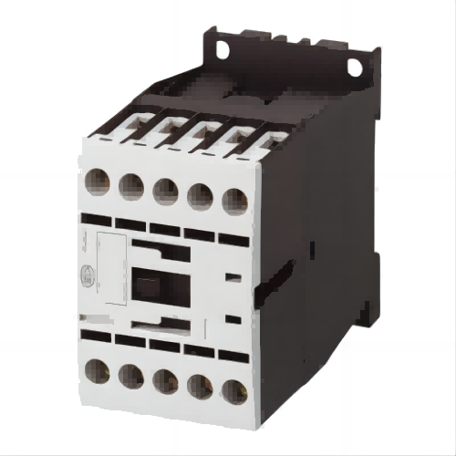
DILK Contactors for capacitors
| Product Weight | 1.02 kg |
| Product Length/Depth | 147 mm |
| Product Height | 190 mm |
| Product Width | 55 mm |
Contactors for power factor correction
Eaton Moeller® series DILK Contactor for capacitors, with series resistors, 33.3 kVAr, 190 V 50 Hz, 220 V 60 Hz
Key technical data includes Ambient operating temperature - max: 60 °C; Ambient operating temperature - min: -25 °C; Ambient operating temperature (enclosed) - max: 40 °C.
| General Information | |
|---|---|
| Product Name | Eaton Moeller® series DILK capacity contactor |
| Catalog Number | 294052 |
| Model Code | DILK33-10(190V50HZ,220V60HZ) |
| EAN | 4015082940522 |
| Product Length/Depth | 147 mm |
| Product Height | 190 mm |
| Product Width | 55 mm |
| Product Weight | 1.02 kg |
| Certifications | CSA C22.2.; UL Listed; IEC 60947-4-1; EN 60947-4-1; CSA Class No.: 3211-04; IEC/EN 60947; UL File No.: E29096; UL; CE; CSA; CSA File No.: 012528; CSA-C22.2 No. 60947-4-1-14; IEC/EN 60947-4-1; UL Category Control No.: NLDX; UL 60947-4-1 |
| Application | Contactors for power factor correction |
| Connection | Screw terminals |
| Degree of protection | IP00 |
| Lifespan, electrical | 150,000 Operations |
| Operating frequency | 120 Operations/h |
| Product category | DILK Contactors for capacitors |
| Protection | Finger and back-of-hand proof, Protection against direct contact when actuated from front (EN 50274) |
| Voltage type | AC |
| Standards & Design Verification | |
|---|---|
| 10.10 Temperature rise | The panel builder is responsible for the temperature rise calculation. Eaton will provide heat dissipation data for the devices. |
| 10.11 Short-circuit rating | Is the panel builder's responsibility. The specifications for the switchgear must be observed. |
| 10.12 Electromagnetic compatibility | Is the panel builder's responsibility. The specifications for the switchgear must be observed. |
| 10.13 Mechanical function | The device meets the requirements, provided the information in the instruction leaflet (IL) is observed. |
| 10.2.2 Corrosion resistance | Meets the product standard's requirements. |
| 10.2.3.1 Verification of thermal stability of enclosures | Meets the product standard's requirements. |
| 10.2.3.2 Verification of resistance of insulating materials to normal heat | Meets the product standard's requirements. |
| 10.2.3.3 Resist. of insul. mat. to abnormal heat/fire by internal elect. effects | Meets the product standard's requirements. |
| 10.2.4 Resistance to ultra-violet (UV) radiation | Meets the product standard's requirements. |
| 10.2.5 Lifting | Does not apply, since the entire switchgear needs to be evaluated. |
| 10.2.6 Mechanical impact | Does not apply, since the entire switchgear needs to be evaluated. |
| 10.2.7 Inscriptions | Meets the product standard's requirements. |
| 10.3 Degree of protection of assemblies | Does not apply, since the entire switchgear needs to be evaluated. |
| 10.4 Clearances and creepage distances | Meets the product standard's requirements. |
| 10.5 Protection against electric shock | Does not apply, since the entire switchgear needs to be evaluated. |
| 10.6 Incorporation of switching devices and components | Does not apply, since the entire switchgear needs to be evaluated. |
| 10.7 Internal electrical circuits and connections | Is the panel builder's responsibility. |
| 10.8 Connections for external conductors | Is the panel builder's responsibility. |
| 10.9.2 Power-frequency electric strength | Is the panel builder's responsibility. |
| 10.9.3 Impulse withstand voltage | Is the panel builder's responsibility. |
| 10.9.4 Testing of enclosures made of insulating material | Is the panel builder's responsibility. |
| Equipment heat dissipation, current-dependent Pvid | 6.6 W |
| Heat dissipation capacity Pdiss | 0 W |
| Heat dissipation per pole, current-dependent Pvid | 2.2 W |
| Rated operational current for specified heat dissipation (In) | 40 A |
| Static heat dissipation, non-current-dependent Pvs | 4.1 W |
| Electrical Characteristics | |
|---|---|
| Rated operational current (Ie) | 50 A at 525 V (three-phase capacitors, open); 45 A at 690 V (three-phase capacitors, enclosed); 45 A at 230 V (three-phase capacitors, enclosed); 45 A at 400 V (three-phase capacitors, enclosed); 50 A at 230 V (three-phase capacitors, open); 50 A at 400 V (three-phase capacitors, open); 50 A at 690 V (three-phase capacitors, open); 45 A at 525 V (three-phase capacitors, enclosed) |
| Rated operational power at AC-6B, 220/230 V, 50 Hz | 20 kW |
| Rated operational power at AC-6B, 380/400 V, 50 Hz | 33.3 kW |
| Rated operational power at AC-6B, 525 V, 50 Hz | 40 kW |
| Rated operational power at AC-6B, 690 V, 50 Hz | 55 kW |
| Coil & Magnet System | |
|---|---|
| Arcing time | 10 ms |
| Drop-out voltage | AC operated: 0.6 - 0.3 x UC, AC operated |
| Duty factor | 100 % |
| Pick-up voltage | 0.8 - 1.15 V AC x Uc |
| Power consumption, pick-up, 50 Hz | 45 VA, Dual-frequency coil in a cold state and 1.0 x Us, at 50 Hz |
| Power consumption, pick-up, 60 Hz | 45 VA, Dual-frequency coil in a cold state and 1.0 x Us, at 60 Hz |
| Power consumption, sealing, 50 Hz | 1.5 VA, Dual-frequency coil in a cold state and 1.0 x Us, at 50 Hz; 4.1 W, Dual-frequency coil in a cold state and 1.0 x Us, at 50 Hz |
| Power consumption, sealing, 60 Hz | 4.1 W, Dual-frequency coil in a cold state and 1.0 x Us, at 60 Hz; 1.5 VA, Dual-frequency coil in a cold state and 1.0 x Us, at 60 Hz |
| Rated control supply voltage (Us) at AC, 50 Hz - max | 190 V |
| Rated control supply voltage (Us) at AC, 50 Hz - min | 190 V |
| Rated control supply voltage (Us) at AC, 60 Hz - max | 220 V |
| Rated control supply voltage (Us) at AC, 60 Hz - min | 220 V |
| Switching time (AC operated, make contacts, closing delay) - min | 50 ms |
| Switching time (AC operated, make contacts, opening delay) - min | 40 ms |
| Terminal Capacities | |
|---|---|
| Terminal capacity (copper band) | 1 x (6 x 9 x 0.8) mm (Number of segments x width x thickness), Main cables |
| Terminal capacity (solid) | 1 x (2.5 - 16) mm², Main cables |
| Terminal capacity (stranded) | 1 x (16 - 50) mm², Main cables |
| Terminal capacity (flexible with ferrule) | 1 x (2.5 - 35) mm², Main cables |
| Terminal capacity (solid/stranded AWG) | 12 - 2, Main Cables |
| Additional Specifications | |
|---|---|
| Emitted interference | According to EN 60947-1 |
| Interference immunity | According to EN 60947-1 |
| Fitted with: | Series resistors |
| Special purpose rating of capacitor switching | 40 kVar, 480 V 60 Hz 3phase, (UL/CSA); 50 kVar, 600 V 60 Hz 3phase, (UL/CSA); 20 kVar, 240 V 60 Hz 3phase, (UL/CSA); 48 A, 240 V 60 Hz 3phase, (UL/CSA); 48 A, 600 V 60 Hz 3phase, (UL/CSA); 48 A, 480 V 60 Hz 3phase, (UL/CSA) |
| Switching capacity (auxiliary contacts, general use) | 10 A, 600 V AC, (UL/CSA); 1 A, 250 V DC, (UL/CSA) |
| Switching capacity (auxiliary contacts, pilot duty) | A600, AC operated (UL/CSA); P300, DC operated (UL/CSA) |
| Ambient operating temperature - max | 60 °C |
| Ambient operating temperature - min | -25 °C |
| Ambient operating temperature (enclosed) - max | 40 °C |
| Ambient operating temperature (enclosed) - min | 25 °C |
| Number of main contacts (normally open contact) | 3 |
| Making capacity without damping (I-peak value) | 180 x Ie |
| Number of auxiliary contacts (normally closed contacts) | 0 |
| Number of auxiliary contacts (normally open contacts) | 1 |
| Number of contacts (normally closed) as main contact | 0 |
Note: Specifications are taken from the official Eaton DILK33-10(190V50HZ,220V60HZ) product data sheet.
Official technical documentation for the DILK33-10(190V50HZ,220V60HZ).
Typical applications of the DILK33-10(190V50HZ,220V60HZ).
Other models in the Eaton Contactors product series.