Authorized Distributor
?
Contactors
| Product Weight | 6.71 kg |
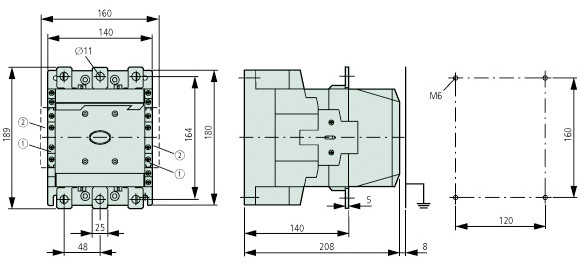
| Product Length/Depth | 208 mm |
| Product Height | 189 mm |
| Product Width | 140 mm |
| Degree Of Protection | IP00 |
| Connection | Screw terminals |
Motor Control, Pumps & Fans, HVAC Systems and more.
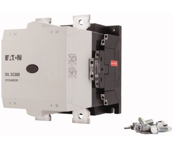
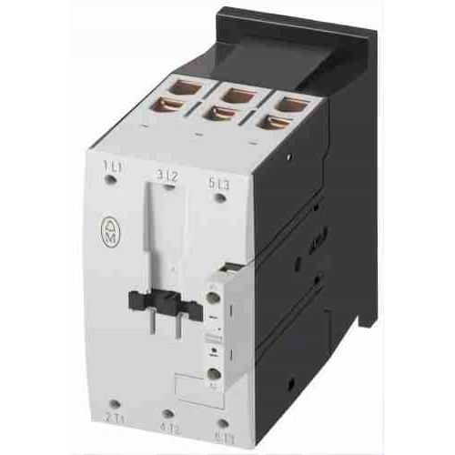
Eaton Moeller® series DILM Contactor supplied by Eaton rated 250 A at 1000 V.
Key performance data includes Product type: Contactors, breaking capacity 2500 A, designed for Contactors for Motors.
Typical applications include Motor Control, Pumps & Fans, HVAC Systems and more.
| General Information | |
|---|---|
| Product Name | Eaton Moeller® series DILM Contactor |
| Catalog Number | 274190 |
| EAN | 4015082741907 |
| Product category | Contactors |
| Voltage type | AC |
| Short-circuit protection rating (type 1 coordination) at 1000 V | 200 A gG/gL |
| Short-circuit protection rating (type 1 coordination) at 400 V | 400 A gG/gL |
| Short-circuit protection rating (type 1 coordination) at 690 V | 400 A gG/gL |
| Short-circuit protection rating (type 2 coordination) at 1000 V | 160 A gG/gL |
| Short-circuit protection rating (type 2 coordination) at 400 V | 315 A gG/gL |
| Short-circuit protection rating (type 2 coordination) at 690 V | 315 A gG/gL |
| Electrical Characteristics | |
|---|---|
| Lifespan, electrical | 100,000 Operations (at Condensor operation) |
| Lifespan, mechanical | 10,000,000 Operations (AC operated) |
| Operating frequency | 3000 mechanical Operations/h (AC operated) 200 Operations/h |
| Overvoltage category | III |
| Rated impulse withstand voltage (Uimp) | 8000 V AC |
| Resistance | 500 mΩ (Admissible transitional contact resistance - of the external control circuit device when actuating A11) |
| Shock resistance | 10 g, N/O main contact, Mechanical, according to IEC/EN 60068-2-27, Half-sinusoidal shock 10 ms 8 g, N/C auxiliary contact, Mechanical, according to IEC/EN 60068-2-27, Half-sinusoidal shock 10 ms 10 g, N/O auxiliary contact, Mechanical, according to IEC/EN 60068-2-27, Half-sinusoidal shock 10 ms |
| Utilization category | AC-4: Normal AC induction motors: starting, plugging, reversing, inching AC-1: Non-inductive or slightly inductive loads, resistance furnaces AC-3: Normal AC induction motors: starting, switch off during running |
| Inrush current | Max. 30 x Ie (peak) |
| Rated breaking capacity at 220/230 V | 2500 A |
| Rated breaking capacity at 380/400 V | 2500 A |
| Rated breaking capacity at 500 V | 2500 A |
| Rated breaking capacity at 660/690 V | 2500 A |
| Rated breaking capacity at 1000 V | 760 A |
| Rated insulation voltage (Ui) | 1000 V |
| Rated making capacity (cos phi to IEC/EN 60947) | 3000 A |
| Rated operational current (Ie) | 220 A at up to 525 V (Individual compensation, three-phase capacitors, open) 133 A at 690 V (Individual compensation, three-phase capacitors, open) |
| Rated operational current (Ie) at AC-1, 380 V, 400 V, 415 V | 430 A |
| Rated operational current (Ie) at AC-3, 220 V, 230 V, 240 V | 250 A |
| Rated operational current (Ie) at AC-3, 380 V, 400 V, 415 V | 250 A |
| Rated operational current (Ie) at AC-3, 440 V | 250 A |
| Rated operational current (Ie) at AC-3, 500 V | 250 A |
| Rated operational current (Ie) at AC-3, 660 V, 690 V | 185 A |
| Rated operational current (Ie) at AC-3, 1000 V | 76 A |
| Rated operational current (Ie) at AC-4, 220 V, 230 V, 240 V | 200 A |
| Rated operational current (Ie) at AC-4, 440 V | 200 A |
| Rated operational current (Ie) at AC-4, 500 V | 200 A |
| Rated operational current (Ie) at AC-4, 660 V, 690 V | 150 A |
| Rated operational current (Ie) at AC-4, 1000 V | 76 A |
| Rated operational power at AC-3, 240 V, 50 Hz | 85 kW |
| Rated operational power at AC-3, 380/400 V, 50 Hz | 132 kW |
| Rated operational power at AC-3, 415 V, 50 Hz | 143 kW |
| Rated operational power at AC-3, 440 V, 50 Hz | 152 kW |
| Rated operational power at AC-3, 500 V, 50 Hz | 173 kW |
| Rated operational power at AC-3, 690 V, 50 Hz | 170 kW |
| Rated operational power at AC-3, 1000 V, 50 Hz | 108 kW |
| Rated operational power at AC-4, 220/230 V, 50 Hz | 62 kW |
| Rated operational power at AC-4, 240 V, 50 Hz | 68 kW |
| Rated operational power at AC-4, 415 V, 50 Hz | 117 kW |
| Rated operational power at AC-4, 440 V, 50 Hz | 125 kW |
| Rated operational power at AC-4, 500 V, 50 Hz | 138 kW |
| Rated operational power at AC-4, 660/690 V, 50 Hz | 137 kW |
| Rated operational voltage (Ue) at AC - max | 1000 V |
| Rated operational power at AC-4, 1000 V, 50 Hz | 108 kW |
| Safe isolation | 500 V AC, Between coil and contacts, According to EN 61140 500 V AC, Between the contacts, According to EN 61140 |
| Short-circuit current rating (basic rating) | 700 A, max. Fuse, SCCR (UL/CSA) 18 kA, SCCR (UL/CSA) 600 A, max. CB, SCCR (UL/CSA) |
| Short-circuit current rating (high fault at 480 V) | 250 A, max. CB, SCCR (UL/CSA) 65 kA, CB, SCCR (UL/CSA) 18 kA, Fuse, SCCR (UL/CSA) 700 A, Class L, max. Fuse, SCCR (UL/CSA) 700 A, Class L/450 A, Class J, max. Fuse, SCCR (UL/CSA) 18/100 kA, Fuse, SCCR (UL/CSA) |
| Short-circuit current rating (high fault at 600 V) | 18 kA, CB, SCCR (UL/CSA) 18 kA, Fuse, SCCR (UL/CSA) 700 A, Class J, max. Fuse, SCCR (UL/CSA) 600 A, max. CB, SCCR (UL/CSA) 700 A, Class L/450 A, Class J, max. Fuse, SCCR (UL/CSA) 18/100 kA, Fuse, SCCR (UL/CSA) |
| Conventional thermal current Ith (1-pole, enclosed) | 750 A |
| Conventional thermal current Ith (3-pole, enclosed) | 300 A |
| Conventional thermal current Ith at 55°C (3-pole, open) | 365 A |
| Conventional thermal current Ith of main contacts (1-pole, open) | 875 A |
| Switching capacity (main contacts, general use) | 350 A, Maximum motor rating (UL/CSA) |
| Switching capacity (auxiliary contacts, general use) | 1 A, 250 V DC, (UL/CSA) 15 A, 600 V AC, (UL/CSA) |
| Switching capacity (auxiliary contacts, pilot duty) | P300, DC operated (UL/CSA) A600, AC operated (UL/CSA) |
| Drop-out voltage | AC operated: 0.2 x US max - 0.4 x US min, AC operated AC operated: 0.25 x US max - 0.6 x US min, AC operated |
| Duty factor | 100 % |
| Pick-up voltage | 0.85 - 1.1 V AC x Us |
| Power consumption | Control transformer with uk ≤ 10% |
| Power consumption, pick-up, 50 Hz | 325 W, Pull-in power, Coil in a cold state and 1.0 x Us 360 VA, Pull-in power, Coil in a cold state and 1.0 x Us |
| Power consumption, pick-up, 60 Hz | 360 VA, Pull-in power, Coil in a cold state and 1.0 x Us 325 W, Pull-in power, Coil in a cold state and 1.0 x Us |
| Power consumption, sealing, 50 Hz | 7.3 VA, Coil in a cold state and 1.0 x Us 4.8 W, Coil in a cold state and 1.0 x Us |
| Power consumption, sealing, 60 Hz | 7.3 VA, Coil in a cold state and 1.0 x Us 4.8 W, Coil in a cold state and 1.0 x Us |
| Rated control supply voltage (Us) at AC, 50 Hz - min | 220 V |
| Rated control supply voltage (Us) at AC, 50 Hz - max | 240 V |
| Rated control supply voltage (Us) at AC, 60 Hz - min | 220 V |
| Rated control supply voltage (Us) at AC, 60 Hz - max | 240 V |
| Assigned motor power at 200/208 V, 60 Hz, 3-phase | 75 HP |
| Assigned motor power at 230/240 V, 60 Hz, 3-phase | 100 HP |
| Assigned motor power at 460/480 V, 60 Hz, 3-phase | 200 HP |
| Assigned motor power at 575/600 V, 60 Hz, 3-phase | 250 HP |
| Equipment heat dissipation, current-dependent Pvid | 0 W |
| Heat dissipation capacity Pdiss | 0 W |
| Heat dissipation per pole, current-dependent Pvid | 9.33 W |
| Rated operational current for specified heat dissipation (In) | 250 A |
| Static heat dissipation, non-current-dependent Pvs | 4.8 W |
| 10.2.2 Corrosion resistance | Meets the product standard's requirements. |
| 10.2.3.2 Verification of resistance of insulating materials to normal heat | Meets the product standard's requirements. |
| 10.2.4 Resistance to ultra-violet (UV) radiation | Meets the product standard's requirements. |
| 10.9.2 Power-frequency electric strength | Is the panel builder's responsibility. |
| 10.9.3 Impulse withstand voltage | Is the panel builder's responsibility. |
| 10.11 Short-circuit rating | Is the panel builder's responsibility. The specifications for the switchgear must be observed. |
| Mechanical & Physical | |
|---|---|
| Product Length/Depth | 208 mm |
| Product Height | 189 mm |
| Product Width | 140 mm |
| Product Weight | 6.71 kg |
| Connection | Screw terminals |
| Degree of protection | IP00 |
| Fitted with: | Suppressor circuit in actuating electronics |
| Protection | Finger and back-of-hand proof with terminal shroud or terminal block, Protection against direct contact when actuated from front (EN 50274) |
| Terminal capacity (busbar) | 25 mm width, Main connection |
| Terminal capacity (copper band) | Fixing with flat cable terminal or cable terminal blocks; See terminal capacity for cable terminal blocks |
| Terminal capacity (flexible with cable lug) | 50 - 240 mm² |
| Terminal capacity (flexible with ferrule) | 1 x (0.75 - 2.5) mm², Control circuit cables 2 x (0.75 - 2.5) mm², Control circuit cables |
| Terminal capacity (solid) | 2 x (0.75 - 2.5) mm², Control circuit cables 1 x (0.75 - 2.5) mm², Control circuit cables |
| Terminal capacity (solid/stranded AWG) | 2/0 - 500 MCM, Main cables 18 - 14, Control circuit cables |
| Terminal capacity (stranded with cable lug) | 70 - 240 mm² |
| Width across flats | 16 mm |
| Screw size | M10, Terminal screw, Main connections M3.5, Terminal screw, Control circuit cables |
| Screwdriver size | 2, Terminal screw, Control circuit cables, Pozidriv screwdriver |
| Tightening torque | 1.2 Nm, Screw terminals, Control circuit cables 24 Nm, Main cable connection screw/bolt |
| Switching time (AC operated, make contacts, closing delay) - max | 55 ms |
| Switching time (AC operated, make contacts, opening delay) - max | 40 ms |
| Number of auxiliary contacts (normally closed contacts) | 2 |
| Number of auxiliary contacts (normally open contacts) | 2 |
| Number of contacts (normally closed contacts) | 2 |
| Number of contacts (normally open contacts) | 2 |
| 10.3 Degree of protection of assemblies | Does not apply, since the entire switchgear needs to be evaluated. |
| 10.5 Protection against electric shock | Does not apply, since the entire switchgear needs to be evaluated. |
| 10.7 Internal electrical circuits and connections | Is the panel builder's responsibility. |
| 10.8 Connections for external conductors | Is the panel builder's responsibility. |
| 10.9.4 Testing of enclosures made of insulating material | Is the panel builder's responsibility. |
| Environmental & Compliance | |
|---|---|
| Certifications | IEC/EN 60947-4-1 UL File No.: E29096 UL Category Control No.: NLDX VDE 0660 UL 60947-4-1 CSA Class No.: 3211-04 UL/CSA CSA File No. 1017510 North America (UL listed, CSA certified) EN 45545: Fire protection on railway vehicles IEC 61373: Vibration and shock, tested for category 1 class B CE marking |
| Pollution degree | 3 |
| Altitude | Max. 2000 m |
| Ambient operating temperature - min | -40 °C |
| Ambient operating temperature - max | 60 °C |
| Ambient operating temperature (enclosed) - min | -40 °C |
| Ambient operating temperature (enclosed) - max | 40 °C |
| Ambient storage temperature - min | -40 °C |
| Ambient storage temperature - max | 80 °C |
| Climatic proofing | Damp heat, cyclic, to IEC 60068-2-30 Damp heat, constant, to IEC 60068-2-78 |
| 10.10 Temperature rise | The panel builder is responsible for the temperature rise calculation. Eaton will provide heat dissipation data for the devices. |
| Additional Specifications | |
|---|---|
| Catalog Notes | Contacts according to EN 50012Also tested according to AC-3e up to 500 V.Also suitable for motors with efficiency class IE3.EN 45545 - Fire protection on railway vehicles: Fire protection class of all plastics according to UL94: V-0 / plastic weight in total: 1.872 kgConventional thermal current Ith of main contacts (1-pole, open) at 60° |
| Accessories | Fitting options auxiliary contacts: on the side: 2 x DILM820-XHI11(V)-SI; 2 x DILM820-XHI11-SA |
| Application | Contactors for Motors |
| Electromagnetic compatibility | Designed for operation in industrial environments. Its use in residential environments may cause radio-frequency interference, requiring additional noise suppression. |
| Special purpose rating of definite purpose rating | 2050 A, LRA 480 V 60 Hz 3-ph, 100,000 cycles acc. to UL 1995, (UL/CSA) 300 A, FLA 480 V 60 Hz 3-ph, 100,000 cycles acc. to UL 1995, (UL/CSA) 1800 A, LRA 600 V 60 Hz 3-ph, 100,000 cycles acc. to UL 1995, (UL/CSA) 250 A, FLA 600 V 60 Hz 3-ph, 100,000 cycles acc. to UL 1995, (UL/CSA) |
| Behavior in marginal and transitional conditions | Sealing - Pick-up phase (0 - 0.7 x Uc min: Contactor does not switch on Sealing - Pick-up phase (0.7 x Uc min - 1.15 x Uc max): Contactor switches on with certainty Sealing - Voltage interruptions (0 - 0.2 x Uc min ≤ 10 ms: Time is bridged successfully Sealing - Voltage interruptions 0 - 0.2 x Uc min) > 10 ms: Drop-out of the contactor Sealing - Voltage drops (0.2 - 0.6 x Uc min ≤12 ms: Time is bridged successfully Sealing - Voltage drops (0.2 - 0.6 x Uc min) > 12 ms: Drop-out of the contactor Sealing - Excess voltage (1.15 - 1.3 x Uc max): Contactor remains switched on Sealing - Voltage drops (0.6 - 0.7 x Uc min: Contactor remains switched on |
| 10.2.3.1 Verification of thermal stability of enclosures | Meets the product standard's requirements. |
| 10.2.3.3 Resist. of insul. mat. to abnormal heat/fire by internal elect. effects | Meets the product standard's requirements. |
| 10.2.5 Lifting | Does not apply, since the entire switchgear needs to be evaluated. |
| 10.2.6 Mechanical impact | Does not apply, since the entire switchgear needs to be evaluated. |
| 10.2.7 Inscriptions | Meets the product standard's requirements. |
| 10.4 Clearances and creepage distances | Meets the product standard's requirements. |
| 10.6 Incorporation of switching devices and components | Does not apply, since the entire switchgear needs to be evaluated. |
| 10.12 Electromagnetic compatibility | Is the panel builder's responsibility. The specifications for the switchgear must be observed. |
| 10.13 Mechanical function | The device meets the requirements, provided the information in the instruction leaflet (IL) is observed. |
Note: Specifications are taken from the official Eaton DILM250 datasheet.
Official technical documentation for the DILM250.
Typical applications of the DILM250.
Other models in the Eaton Contactors product series.