Authorized Distributor
?
DC Contactor
| Product Weight | 7.5 kg |
| Product Length/Depth | 248 mm |
| Product Height | 219 mm |
| Product Width | 160 mm |
DC contactor
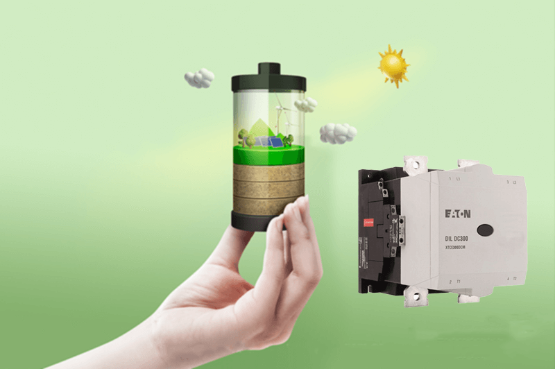
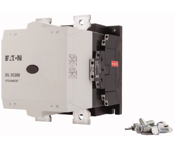
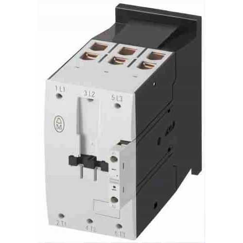
Eaton Moeller® series DILDC DC contactor, 2 N/O, 2 NC, 1000 V: 600 A, RDS 250: 110 - 250 V 40 - 60 Hz/110 - 350 V DC, AC and DC operation
Key technical data includes Global Catalog: 183315; Product Type: DC Contactor; 10.2.2 Corrosion resistance: Meets the product standard's requirements..
| General Information | |
|---|---|
| Product Name | Eaton Moeller® series DILDC DC Contactor |
| Catalog Number | 183315 |
| Model Code | DILDC600/22(RDS250) |
| EAN | 4015081782505 |
| Product Length/Depth | 248 mm |
| Product Height | 219 mm |
| Product Width | 160 mm |
| Product Weight | 7.5 kg |
| Certifications | UL Category Control No.: NRNT UL CSA CSA Class No.: C321124 UL508 IEC/EN 60947-5-1 CSA File No.: 012528 UL File No.: E338590 IEC/EN 60947-4-1 CE CSA-C22.2 No. 14-05 |
| Catalog Notes | DILDC contactors feature an electronic arc suppression system. Because of this, it is important not to exceed any technical data limits in general – especially the making and breaking capacity limits. Opening the device will immediately void the warranty. |
| Global Catalog | 183315 |
| Product Type | DC Contactor |
| Product Specifications | |
|---|---|
| Accessories | Fitting options auxiliary contacts: on the side: 2 x DILM820-XHI11(V)-SI; 2 x DILM820-XHI11-SA |
| 10.10 Temperature rise | The panel builder is responsible for the temperature rise calculation. Eaton will provide heat dissipation data for the devices. |
| 10.11 Short-circuit rating | Is the panel builder's responsibility. The specifications for the switchgear must be observed. |
| 10.12 Electromagnetic compatibility | Is the panel builder's responsibility. The specifications for the switchgear must be observed. |
| 10.13 Mechanical function | The device meets the requirements, provided the information in the instruction leaflet (IL) is observed. |
| 10.2.2 Corrosion resistance | Meets the product standard's requirements. |
| 10.2.3.1 Verification of thermal stability of enclosures | Meets the product standard's requirements. |
| 10.2.3.2 Verification of resistance of insulating materials to normal heat | Meets the product standard's requirements. |
| 10.2.3.3 Resist. of insul. mat. to abnormal heat/fire by internal elect. effects | Meets the product standard's requirements. |
| 10.2.4 Resistance to ultra-violet (UV) radiation | Meets the product standard's requirements. |
| 10.2.5 Lifting | Does not apply, since the entire switchgear needs to be evaluated. |
| 10.2.6 Mechanical impact | Does not apply, since the entire switchgear needs to be evaluated. |
| 10.2.7 Inscriptions | Meets the product standard's requirements. |
| 10.3 Degree of protection of assemblies | Does not apply, since the entire switchgear needs to be evaluated. |
| 10.4 Clearances and creepage distances | Meets the product standard's requirements. |
| 10.5 Protection against electric shock | Does not apply, since the entire switchgear needs to be evaluated. |
| 10.6 Incorporation of switching devices and components | Does not apply, since the entire switchgear needs to be evaluated. |
| 10.7 Internal electrical circuits and connections | Is the panel builder's responsibility. |
| 10.8 Connections for external conductors | Is the panel builder's responsibility. |
| 10.9.2 Power-frequency electric strength | Is the panel builder's responsibility. |
| 10.9.3 Impulse withstand voltage | Is the panel builder's responsibility. |
| 10.9.4 Testing of enclosures made of insulating material | Is the panel builder's responsibility. |
| Operating frequency | 100 electrical Operations/h 1000 mechanical Operations/h (DC operated) 1000 mechanical Operations/h (AC operated) |
| Pollution degree | 3 |
| Climatic proofing | Damp heat, constant, to IEC 60068-2-78 Damp heat, cyclic, to IEC 60068-2-30 |
| Rated impulse withstand voltage (Uimp) | 8000 V DC |
| Ambient operating temperature - max | 70 °C |
| Ambient operating temperature - min | -40 °C |
| Ambient operating temperature (enclosed) - max | 40 °C |
| Ambient operating temperature (enclosed) - min | -40 °C |
| Ambient storage temperature - max | 80 °C |
| Ambient storage temperature - min | -40 °C |
| Equipment heat dissipation, current-dependent Pvid | 0 W |
| Heat dissipation capacity Pdiss | 0 W |
| Heat dissipation per pole, current-dependent Pvid | 72 W |
| Number of auxiliary contacts (normally closed contacts) | 2 |
| Number of auxiliary contacts (normally open contacts) | 2 |
| Number of contacts (normally closed contacts) | 2 |
| Number of contacts (normally closed) as main contact | 0 |
| Number of contacts (normally open contacts) | 2 |
| Number of main contacts (normally open contact) | 2 |
| Rated breaking capacity at 1000 V | 900 A |
| Rated breaking capacity at 220/230 V | 900 A |
| Rated breaking capacity at 380/400 V | 900 A |
| Rated breaking capacity at 500 V | 900 A |
| Rated breaking capacity at 660/690 V | 900 A |
| Switching time (AC operated, make contacts, opening delay) - max | 40 ms |
| Application | DC contactor |
| Product category | Contactors |
| Electrical connection type of main circuit | Connection rail |
| Screwdriver size | 2, Terminal screw, Control circuit cables, Pozidriv screwdriver 0.8 x 5.5/1 x 6 mm, Terminal screw, Control circuit cables, Standard screwdriver |
| Voltage type | DC |
| Degree of protection | IP00 |
| Drop-out voltage | 0.2 x US max - 0.6 x US min, DC operated AC operated: 0.2 x US max - 0.6 x US min, AC operated |
| Overvoltage category | III |
| Duty factor | 100 % |
| Electromagnetic compatibility | Designed for operation in industrial environments. Its use in residential environments may cause radio-frequency interference, requiring additional noise suppression. |
| Lifespan, mechanical | 1,000,000 Operations (DC operated) 1,000,000 Operations (AC operated) |
| Pick-up voltage | 0.7 - 1.15 V DC x Us 0.7 - 1.15 V AC x Us |
| Power consumption, pick-up, 50 Hz | 575 VA, Pull-in power, Coil in a cold state and 1.0 x Us |
| Safe isolation | 1000 V, Between auxiliary contacts and main contacts, According to EN 61140 1000 V, Between control inputs and main contacts, According to EN 61140 1000 V, Between the contacts, According to EN 61140 |
| Power consumption, pick-up, 60 Hz | 575 VA, Pull-in power, Coil in a cold state and 1.0 x Us |
| Screw size | M3.5, Terminal screw, Control circuit cables M10, Terminal screw, Main connections |
| Power consumption, sealing, 50 Hz | 9.5 W, Coil in a cold state and 1.0 x Us 18 VA, Coil in a cold state and 1.0 x Us |
| Power consumption, sealing, 60 Hz | 18 VA, Coil in a cold state and 1.0 x Us 9.5 W, Coil in a cold state and 1.0 x Us |
| Rated control supply voltage (Us) at AC, 50 Hz - max | 250 V |
| Rated control supply voltage (Us) at AC, 50 Hz - min | 110 V |
| Rated control supply voltage (Us) at AC, 60 Hz - max | 250 V |
| Rated control supply voltage (Us) at AC, 60 Hz - min | 110 V |
| Rated control supply voltage (Us) at DC - max | 350 V |
| Rated control supply voltage (Us) at DC - min | 110 V |
| Rated insulation voltage (Ui) at DC | 1000 V |
| Rated making capacity (cos phi to IEC/EN 60947) | 900 A |
| Rated operational current (Ie) at DC-1, 1000 V | 600 A |
| Rated operational current for specified heat dissipation (In) | 600 A |
| Rated operational voltage (Ue) at DC - max | 1000 V |
| Static heat dissipation, non-current-dependent Pvs | 9 W |
| Switching time (AC operated, make contacts, closing delay) - max | 80 ms |
| Switching capacity (auxiliary contacts, general use) | 1 A, 250 V DC, (UL/CSA) 15 A, 600 V AC, (UL/CSA) |
| Switching capacity (auxiliary contacts, pilot duty) | P300, DC operated (UL/CSA) A600, AC operated (UL/CSA) |
| Terminal capacity (flexible with ferrule) | 1 x (0.75 - 2.5) mm², Control circuit cales 1 x (0.75 - 2.5) mm², Control circuit cables |
| Shock resistance | 10 g, N/O auxiliary contact, Mechanical, according to IEC/EN 60068-2-27, Half-sinusoidal shock 10 ms 8 g, N/C auxiliary contact, Mechanical, according to IEC/EN 60068-2-27, Half-sinusoidal shock 10 ms 10 g, N/O main contact, Mechanical, according to IEC/EN 60068-2-27, Half-sinusoidal shock 10 ms |
| Terminal capacity (solid) | 1 x (0.75 - 2.5) mm², Control circuit cales 1 x (0.75 - 2.5) mm², Control circuit cables |
| Short-circuit protection rating | Max. 900 A gR 1000 V DC (max. short-circuit current 6 kA), Fuse, Type “2” coordination, 400 V DC, Main conducting paths Max. 900 A gR 1000 V DC (max. short-circuit current 30 kA), Fuse, Type “1” coordination, 1000 V DC, Main conducting paths Max. 900 A gR 1000 V DC (max. short-circuit current 6 kA), Fuse, Type “2” coordination, 690 V DC, Main conducting paths Max. 900 A gR 1000 V DC (max. short-circuit current 6 kA), Fuse, Type “2” coordination, 1000 V DC, Main conducting paths Max. 900 A gR 1000 V DC (max. short-circuit current 30 kA), Fuse, Type “1” coordination, 400 V DC, Main conducting paths |
| Terminal capacity (solid/stranded AWG) | 1/0 - 500 MCM, Main cables 2 x (18 - 12) |
| Signal level | 5 V - 15 V, PLC signal level (A3 - A4) to IEC/EN 61131-2 (type 2), Magnet systems |
| Terminal capacity (busbar) | 40 mm width, Main connection |
| Terminal capacity (flexible with cable lug) | 50 - 240 mm² |
| Switching capacity (main contacts, general use) | 600 A, Maximum motor rating, Single-phase (UL/CSA) |
| Terminal capacity (stranded with cable lug) | 50 - 240 mm² |
| Tightening torque | 1.2 Nm, Screw terminals, Control circuit cables 24 Nm, Main cable connection screw/bolt |
| Width across flats | 16 mm |
| Operating voltage at DC - min | 110 V |
| Operating voltage at DC - max | 350 V |
| Thu Oct 29 2026 | |
| Eaton Moeller® series DILDC DC Contactor | |
| 183315 | |
| DILDC600/22(RDS250) | |
| 4015081782505 | |
| 248 mm | |
| 219 mm | |
| 160 mm | |
| 7.5 kg | |
| UL Category Control No.: NRNT | |
| DILDC contactors feature an electronic arc suppression system. Because of this, it is important not to exceed any technical data limits in general – especially the making and breaking capacity limits. Opening the device will immediately void the warranty. | |
| 183315 | |
| DC Contactor | |
| Fitting options auxiliary contacts: on the side: 2 x DILM820-XHI11(V)-SI; 2 x DILM820-XHI11-SA | |
| The panel builder is responsible for the temperature rise calculation. Eaton will provide heat dissipation data for the devices. | |
| Is the panel builder's responsibility. The specifications for the switchgear must be observed. | |
| Is the panel builder's responsibility. The specifications for the switchgear must be observed. | |
| The device meets the requirements, provided the information in the instruction leaflet (IL) is observed. | |
| Meets the product standard's requirements. | |
| Meets the product standard's requirements. | |
| Meets the product standard's requirements. | |
| Meets the product standard's requirements. | |
| Meets the product standard's requirements. | |
| Does not apply, since the entire switchgear needs to be evaluated. | |
| Does not apply, since the entire switchgear needs to be evaluated. | |
| Meets the product standard's requirements. | |
| Does not apply, since the entire switchgear needs to be evaluated. | |
| Meets the product standard's requirements. | |
| Does not apply, since the entire switchgear needs to be evaluated. | |
| Does not apply, since the entire switchgear needs to be evaluated. | |
| Is the panel builder's responsibility. | |
| Is the panel builder's responsibility. | |
| Is the panel builder's responsibility. | |
| Is the panel builder's responsibility. | |
| Is the panel builder's responsibility. | |
| 100 electrical Operations/h | |
| 3 | |
| Damp heat, constant, to IEC 60068-2-78 | |
| 8000 V DC | |
| 70 °C | |
| -40 °C | |
| 40 °C | |
| -40 °C | |
| 80 °C | |
| -40 °C | |
| 0 W | |
| 0 W | |
| 72 W | |
| 2 | |
| 2 | |
| 2 | |
| 0 | |
Note: Specifications are taken from the official Eaton DILDC600/22(RDS250) product data sheet.
Official technical documentation for the DILDC600/22(RDS250).
Typical applications of the DILDC600/22(RDS250).
Other models in the Eaton Contactors product series.